The Weight Estimator program was develop by JMC McAlester to assist in characterizing munitions. It calculates volumes, surface areas and their associated weights based on material densities.
There are over 50 different shapes that can be selected to estimate the weight. Each shape has unique dimensions that can be entered. However, care must be taken to enter realistic dimensions since the system does not currently do any input validation. For example, it is possible to enter an inside radius larger than an outside radius for spheres or cylinders. However, the 3D model will help indicate impossible shapes by trying to generate unrealistic shapes. If the shape does not look correct, then the input values are most likely incorrect.
The 3D model for each shape is updated when you click on the "Update 3D Model". This will give an exact scale representation of the model. You can use the mouse to rotate and move the model. The scroll wheel will zoom the model in and out. Each time you update the model, it will reset to the initial view size and direction.
Each shape page also has a Help Link that accesses this help page. There is basic information for each shape, particularly if there are special conditions that should be noted.
The Anchor Pin object has two tapering conical sections, one at the top and one at the bottom. Both conical sections are assumed to taper inward towards the top. The middle section is a simple cylinder.
All sections are considered to be solid.
Technical Calculations
The equation for a tapered cylinder section is derived in the "Solid Ogive" (not a real ogive shape). The derivation will not be duplicated here. The the tapered cylinder volumes are
VTop Tapered Cyl = π D (E2 + F2 + EF) /12
VBottom Tapered Cyl = π B (F2 + A2 + FA) /12
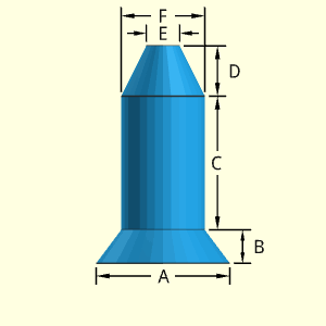
The outside surface area is just the average perimeter times the slope length (see "Solid Ogive" for derivation). This equation is only for the side and does not include the circular area at the top or bottom.
STop Tapered Side = [π(F + E)/2] [(F - E)2/4 + D2]0.5
SBottom Tapered Side = [π(A + F)/2] [(A - F)2/4 + B2]0.5
Outer Surface Area, Aouter, consists of two tapered cylinders, top and and bottom circular area, and one solid cylinder side,
Aouter = [π(F + E)/2] [(F - E)2/4 + D2]0.5 + π F C
+ [π(A + F)/2] [(A - F)2/4 + B2]0.5
+ π E2/4 + π A2/4
Inner Surface Area, Ainner, no inside surface,
Ainner = 0
ATotal = Aouter + Ainner
Volume, V, consists of two solid tapered cylinders and on solid cylinder
V = π D (E2 + F2 + EF) /12 + π F2C/4
+ π B (F2 + A2 + FA) /12
| Value | Equations | WE Program |
| Case 1 | ||
| Surface Area | 267.0 in2 | 267.0 in2 |
| Volume | 255.3 in3 | |
| Part Weight | 9.222 lb | 9.222 lb |
| Case 2 | ||
| Surface Area | 508.0 cm2 | 508.0 cm2 |
| Volume | 728.8 cm3 | |
| Part Weight | 1.607 lb | 1.607 lb |
| Case Number | ||
| Parameter | 1 | 2 |
| A | 8 in | 12 cm |
| B | 2 in | 3 cm |
| C | 8 in | 8 cm |
| D | 3 in | 3 cm |
| E | 2 in | 4 cm |
| F | 5 in | 8 cm |
| test density |
1 gm/cm3 | 1 gm/cm3 |
Conversion Constants to
determine part weight in lb
1 gm/cm3 = 2.2046×10⁻⁶ lb/mm3
= 0.036127 lb/in3
The Block object is a multiple indented shape that can be used for various rectangular configurations. Each of the protrusions on the top can be a different height and thickness. One should be careful not to have one protrusion go negatively into another. The program does allow unrealistic shapes to be constructed with the 3D modeler.

Technical Calculations
Outer Surface Area, Aouter, consists of both top and bottom surface, plus the perimeter of the block. The top and bottom is divided into rectangular parts and added. The perimeter is just added using the dimensions in the diagram. Notice, B is the same as the bottom and top,
Aouter = Atop-bottom + Aedge
= 2[E(D - H) + DF + G(C - I) + C(B - E - F - G)]
+ A[B + C + B + I + (D + I - C) + H + (D - H)]
= 2[ED - EH + DF - GI + CB - CE - CF]
+ A[2B + 2D + 2I]
Inner Surface Area, Ainner, no inside surface,
Ainner = 0
ATotal = Aouter + Ainner
Volume, V, consists of the block surface times the depth. Use the top area given above in the outer surface derivation,
V = A[ED - EH + DF - GI + CB - CE - CF]

| Value | Equations | WE Program | Graphic* |
| Case 1 | |||
| Surface Area | 98.00 in2 | 98.00 in2 | |
| Volume | 48.00 in3 | ||
| Part Weight | 1.734 lb | 1.734 lb | |
| Case 2 | |||
| Surface Area | 274.0 cm2 | 274.0 cm2 | 274.0 cm2 |
| Volume | 210.0 cm3 | 210 cm3 | |
| Part Weight | 0.4630 lb | 0.4630 lb |
*Use diagram to count squares for area, perimeter
and volume
| Case Number | ||
| Parameter | 1 | 2 |
| A | 3 in | 5 cm |
| B | 5 in | 8 cm |
| C | 5 in | 8 cm |
| D | 4 in | 6 cm |
| E | 2 in | 1 cm |
| F | 1 in | 3 cm |
| G | 1 in | 2 cm |
| H | 2 in | 4 cm |
| I | 2 in | 5 cm |
| test density |
1 gm/cm3 | 1 gm/cm3 |
Conversion Constants to
determine part weight in lb
1 gm/cm3 = 2.2046×10⁻⁶ lb/mm3
= 0.036127 lb/in3
17 Dec 2020 - Kurt Gramoll
1) Surface equations incorrectly included inner surface with outer surface. New equation separated outer and inner surfaces.
The Solid Bolt object has an hexagon shape top and cylindrical shape shaft. The dimension A is from one side of the hexagon to the opposite side. The dimension A is not a single side width. It is assumed that the hexagonal head and cylindrical shaft are in line vertically.
Technical Calculations
Outer Surface Area, Aouter,
Aouter = 2 [(30.5/2) A2] - πC2/4 + πCD + πC2/4
+ 6 AB / 30.5
= 30.5A2 + πCD + 30.52AB
Inner Surface Area, Ainner, does not exist.
Ainner = 0
ATotal = Aouter + Ainner
Volume, V, consists of a single sphere.
V = (30.5/2)A2B + πC2D/4

| Value | Equations | WE Program |
| Case 1 | ||
| Surface Area | 125.1 in2 | 125.1 in2 |
| Volume | 78.64 in3 | |
| Part Weight | 2.841 lb | 2.841 lb |
| Case 2 | ||
| Surface Area | 38.55 cm2 | 38.55 cm2 |
| Volume | 10.94 cm3 | |
| Part Weight | 0.02411 lb | 0.02411 lb |
| Case Number | ||
| Parameter | 1 | 2 |
| A | 5 in | 3 cm |
| B | 2 in | 1 cm |
| C | 3 in | 1 cm |
| D | 5 in | 4 cm |
| test density |
1 gm/cm3 | 1 gm/cm3 |
Conversion Constants to
determine part weight in lb
1 gm/cm3 = 2.2046×10⁻⁶ lb/mm3
= 0.036127 lb/in3
17 Dec 2020 - Kurt Gramoll
1) Previous equations included an extra circular area equal to the bolt shaft end. The area equations were corrected. Both volume and area equations were simplified.
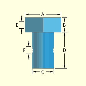
The Bolt with Through Holes object has an hexagon shape top and cylindrical shape shaft. Both the top and shaft can have a single hole completely through the object. Each of the two holes can have different diameters. There is only one hole for each location.
The dimension A is from one side of the hexagon to the opposite side. The dimension A is not a single side width. It is assumed that the hexagonal head and cylindrical shaft are in line vertically.
Technical Calculations
Outer Surface Area, Aouter,
Aouter = 2 [(30.5/2) A2] - πC2/4 + πCD + πC2/4
+ 6 AB / 30.5 - 2E2π/4 - 2FE2π/4
= 30.5A2 + πCD + 30.52AB - π(E2 + F2)/2
Inner Surface Area, Ainner,
Ainner = πEA + πFC
ATotal = Aouter + Ainner
Volume, V, consists of a single sphere.
V = (30.5/2)A2B + πC2D/4 - πE2A/4 - πF2C/4
= (30.5/2)A2B + π(C2D - E2A - F2C)/4
| Value | Equations | WE Program |
| Case 1 | ||
| Surface Area | 147.1 in2 | 147.1 in2 |
| Volume | 72.36 in3 | |
| Part Weight | 2.614 lb | 2.614 lb |
| Case 2 | ||
| Surface Area | 44.04 cm2 | 44.04 cm2 |
| Volume | 10.15 cm3 | |
| Part Weight | 0.022378 lb | 0.022378 lb |
| Case Number | ||
| Parameter | 1 | 2 |
| A | 5 in | 3 cm |
| B | 2 in | 1 cm |
| C | 3 in | 1 cm |
| D | 5 in | 4 cm |
| E | 1 in | 0.5 cm |
| F | 1 in | 0.5 cm |
| test density |
1 gm/cm3 | 1 gm/cm3 |
Conversion Constants to
determine part weight in lb
1 gm/cm3 = 2.2046×10⁻⁶ lb/mm3
= 0.036127 lb/in3
17 Dec 2020 - Kurt Gramoll
1) Previous equations included an extra circular area equal to the bolt shaft end. The area equations were corrected. Both volume and area equations were simplified.
2) Previous equations flipped E and F when calculating inside surface Equation was corrected.
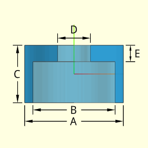
The Cap object is a single cylindrical shape with a hollow cylindrical shape. The bottom is open, but the top is closed with a circular hole. The top closed end thickness is E. The wall thickness is the difference between the diameters A and B, divided by 2.
Technical Calculations
Outer Surface Area, Aouter,
Aouter = πAC + π(A2 - D2)/4 + π(A2 - B2)/4
Inner Surface Area, Ainner,
Ainner = πDE + πB(C - E) + π(B2 - D2)/4
ATotal = Aouter + Ainner
Volume, V, consists of a single sphere.
V = πA2C/4 - πB2(C - E)/4 - πD2E/4
| Value | Equations | WE Program |
| Case 1 | ||
| Surface Area | 647.2 in2 | 647.2 in2 |
| Volume | 373.8 in3 | |
| Part Weight | 13.51 lb | 13.51 lb |
| Case 2 | ||
| Surface Area | 967.6 cm2 | 967.6 cm2 |
| Volume | 892.2 cm3 | |
| Part Weight | 1.967 lb | 1.967 lb |
| Case Number | ||
| Parameter | 1 | 2 |
| A | 12 in | 16 cm |
| B | 10 in | 12 cm |
| C | 7 in | 8 cm |
| D | 4 in | 8 cm |
| E | 2 in | 3 cm |
| test density |
1 gm/cm3 | 1 gm/cm3 |
Conversion Constants to
determine part weight in lb
1 gm/cm3 = 2.2046×10⁻⁶ lb/mm3
= 0.036127 lb/in3
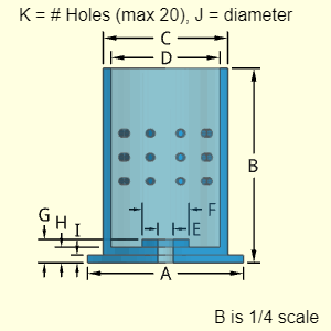
The Cartridge Case object has a cylindrical shaped hollow shell with an open end. The bottom has three different disks, each with a different radius. All three bottom circular plates have a center hole of radius E.
The upper cylindrical shell can up to 20 holes of similar type. The holes are assumed to go through the shell thickness. The location and spacing is not needed for the volume and surface area calculations.
Technical Calculations
Outer Surface Area, Aouter, all shapes are based on cylinders, ,
Aouter = π(A2 - E2) /4 + πA I + π(A2 - C2) /4
+ πC (B - I) - πJ2 K / 4 + π(C2 - D2) /4
Inner Surface Area, Ainner, consists of just the inner surface of the hollow cone,
Ainner = πEG + π(D2 - E2) /4 + πD (B - H)
- πJ2 K /4 + πJ [(C - D)/2] K + πF (G - H)
ATotal = Aouter + Ainner
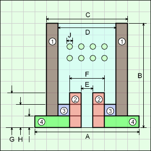
Volume, V, consists several cylindrical hollow shapes. The diagram shows each of the cylindrical shapes that are used to derive the volume equation.
V = V1 + V2 + V3 + V4 + Vholes
= π(C2 - D2) (B - I) /4 + π(F2 - E2) G /4
+ π(D2 - F2) (H - I) /4 + π(A2 - F2) I /4
+ πJ2 [(C - D)/2] * K /4
| Value | Equations | WE Program |
| Case 1 | ||
| Surface Area | 10,028 in2 | 10,028 in2 |
| Volume | 5,143 in3 | |
| Part Weight | 185.8 lb | 185.8 lb |
| Case 2 | ||
| Surface Area | 1920 cm2 | 1920 cm2 |
| Volume | 966.0 cm3 | |
| Part Weight | 2.130 lb | 2.130 lb |
| Case Number | ||
| Parameter | 1 | 2 |
| A | 20 in | 10 cm |
| B | 100 in | 40 cm |
| C | 16 in | 8 cm |
| D | 14 in | 6 cm |
| E | 2 in | 2 cm |
| F | 6 in | 4 cm |
| G | 3 in | 3 cm |
| H | 2 in | 2 cm |
| I | 1 in | 1 cm |
| J | 1 in | 0.5 cm |
| K | 12 | 8 |
| test density |
1 gm/cm3 | 1 gm/cm3 |
Conversion Constants to
determine part weight in lb
1 gm/cm3 = 2.2046×10⁻⁶ lb/mm3
= 0.036127 lb/in3
21 Dec 2020 - Kurt Gramoll
1) Previous equations was missing the inside surface of the small top washer shape, S = πF(G-H) The inside surface area equation was corrected.
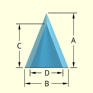
The Hollow Cone object is a basic conical section with a hollow internal cone shape. The wall thickness is not constant, and is dependant on the relative height of the inside hollow cone, C. The horizontal thickness at the base is the difference between radius B and D, divided by 2.
Technical CalculationsOuter Surface Area, Aouter, consists of an outside of the outer cone, and the bottom edge,
Aouter = Acone + Abottom edge
= π (B/2) [ A2 + (B/2)2 ]0.5
+ π [ (B/2)2 - (D/2)2 ]
Inner Surface Area, Ainner, consists of just the inner surface of the hollow cone,
Ainner = π (D/2) [ C2 + (D/2)2 ]0.5
ATotal = Aouter + Ainner
Volume, V, consists of a single cone minus the hollow inner cone.
V = (π/3) [ A (B/2)2 - C (D/2)2 ]
Calculation Caparison
| Value | Equations | WE Program |
| Case 1 | ||
| Surface Area | 59.47 in2 | 59.47 in2 |
| Volume | 11.59 in3 | |
| Part Weight | 0.4162 lb | 0.4162 lb |
| Case 2 | ||
| Surface Area | 504.7 cm2 | 504.7 cm2 |
| Volume | 6.807 cm3 | |
| Part Weight | 0.5218 lb | 0.5218 lb |
Input Values
| Case Number | ||
| Parameter | 1 | 2 |
| A | 5 in | 18 cm |
| B | 4 in | 10 cm |
| C | 4 in | 6 cm |
| D | 3 in | 1 cm |
| test density |
1 gm/cm3 | 1 gm/cm3 |
Conversion Constants to
determine part weight in lb
1 gm/cm3 = 2.2046×10⁻⁶ lb/mm3
= 0.036127 lb/in3
7 Dec 2020 - Kurt Gramoll
1) Inner and outer surface equations were flipped in the program. Changed.
2) Inner equation multiplied the squared radius and squared height terms instead of adding them. Was also incorrect in original code.
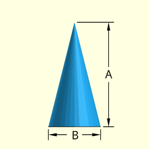
The Cone object is a basic conical shape. The shape is solid and has only two dimensions, height A and base diameter B.
Technical Calculations
Equation details are documented at https://en.wikipedia.org/wiki/Cone
Outer Surface Area, Aouter, consists of a single cone including the bottom,
Aouter= Acone + Abottom
= π (B/2) [ (B/2)2 + A2) ]0.5 + π (B/2)2
Inner Surface Area, Ainner, does not exist.
Ainner = 0
ATotal = Aouter + Ainner
Volume, V, consists of a single cone.
V = (π/3) (B/2)2 A
Calculation Caparison
| Value | Equations | WE Program |
| Case 1 | ||
| Surface Area | 4.024 in2 | 4.024 in2 |
| Volume | 0.5236 in3 | |
| Part Weight | 0.01892 lb | 0.01892 lb |
| Case 2 | ||
| Surface Area | 28.47 cm2 | 28.47 cm2 |
| Volume | 8.378 cm3 | |
| Part Weight | 0.01847 lb | 0.01847 lb |
Input Values
| Case Number | ||
| Parameter | 1 | 2 |
| A | 2 in | 8 cm |
| B | 1 in | 2 cm |
| test density |
1 gm/cm3 | 1 gm/cm3 |
Conversion Constants to
determine part weight in lb
1 gm/cm3 = 2.2046×10⁻⁶ lb/mm3
= 0.036127 lb/in3
The "Hollow Cylinder A and C Closed" object is cylindrical shape that has cylindrical hollow section. Both ends are capped. The wall thickness is the difference between the diameters A and C, divided by 2. Both end cap thickness are the same, but can be different than the wall thickness.
The shape can have one type of hole, but there can be multiple instances of that hole. Each hole is assumed to goes through the wall (no partial indents).
The location of the holes is not needed for volume and surface area calculations. But it is assumed that the holes diameters are not large, and they will be contained inside the cylinder diameter, A and are in the hollow section. Also, it is assumed that a given hole depth does not exceed the cylinder wall thickness.
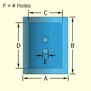
Outer Surface Area, Aouter, consists of the outer main cylinder and the two outside circular ends. Subtract the hole areas.
Aouter = Acylinder + Aends - Ahole ends
= (πA) B + 2 (πA2/4) - F (πE2/4)
Inner Surface Area, Ainner, consists cylindrical inside surface and circular ends. Plus the inside cylindrical surface of the holes minus the end of the hole.
Ainner = Ainside cylinder + Ainside ends
+ Ahole cylinder - Ahole end
= (πC) D + 2 (πC2/4)
+ F (πE) (A-C)/2 - F (πE2/4)
ATotal = Aouter + Ainner
Volume, V, consists of the difference of the outside cylinder minus the hollow inside cylinder. Then subs tract all instances of the holes.
V = (πA2/4) B - (πC2/4) D - F (πE2/4) (A - C)/2
| Value | Equations | WE Program |
| Case 1 | ||
| Surface Area | 562.3 in2 | 562.3 in2 |
| Volume | 274.9 in3 | |
| Part Weight | 9.931 lb | 9.931 lb |
| Case 2 | ||
| Surface Area | 5,171 cm2 | 5,171 cm2 |
| Volume | 6,133.5 cm3 | |
| Part Weight | 13.48 lb | 13.48 lb |
| Case Number | ||
| Parameter | 1 | 2 |
| A | 8 in | 20 cm |
| B | 10 in | 40 cm |
| C | 6 in | 16 cm |
| D | 8 in | 32 cm |
| E | 1 in | 2 cm |
| F | 2 | 3 |
| test density |
1 gm/cm3 | 1 gm/cm3 |
Conversion Constants to
determine part weight in lb
1 gm/cm3 = 2.2046×10⁻⁶ lb/mm3
= 0.036127 lb/in3
The "Hollow Cylinder A and C Open " object is cylindrical shape that has cylindrical hollow section. Both ends are open. This shape could also be described a simple tube. The wall thickness is the difference between the diameters A and C, divided by 2.
The shape can have one type of hole, but there can be multiple instances of that hole. Each hole is assumed to goes through the wall (no partial indents).
The location of the holes is not needed for volume and surface area calculations. But it is assumed that the holes diameters are not large, and are contained inside the cylinder diameter, A. Also, it is assumed that a given hole depth does not exceed the cylinder wall thickness.
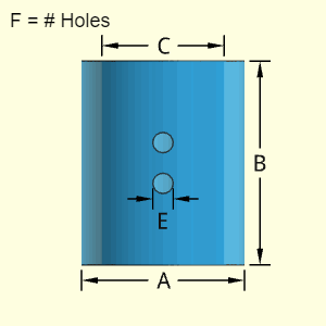
Outer Surface Area, Aouter, consists of the outer main outside cylinder, the two end edges, and the subtraction of the hole areas.
Aouter = Acylinder + Aedge ends - Ahole ends
= (πA) B + 2 π(A2-C2)/4 - F (πE2/4)
Inner Surface Area, Ainner, consists cylindrical inside surface and circular ends. Plus the inside cylindrical surface of the holes minus the end of the hole.
Ainner = Ainside cylinder + Ahole cylinder - Ahole end
= (πC) B + F (πE) (A-C)/2 - F (πE2/4)
ATotal = Aouter + Ainner
Volume, V, consists of the difference of the outside cylinder minus the hollow inside cylinder. Then subs tract all instances of the holes.
V = B π(A2 - C2)/4 - F (πE2/4) (A - C)/2
| Value | Equations | WE Program |
| Case 1 | ||
| Surface Area | 486.9 in2 | 486.9 in2 |
| Volume | 218.3 in3 | |
| Part Weight | 7.888 lb | 7.888 lb |
| Case 2 | ||
| Surface Area | 4,769 cm2 | 4,769 cm2 |
| Volume | 4,505 cm3 | |
| Part Weight | 9.932 lb | 9.932 lb |
| Case Number | ||
| Parameter | 1 | 2 |
| A | 8 in | 20 cm |
| B | 10 in | 40 cm |
| C | 6 in | 16 cm |
| E | 1 in | 2 cm |
| F | 2 | 3 |
| test density |
1 gm/cm3 | 1 gm/cm3 |
Conversion Constants to
determine part weight in lb
1 gm/cm3 = 2.2046×10⁻⁶ lb/mm3
= 0.036127 lb/in3
The "Hollow Cylinder A or C Open " object is cylindrical shape that has cylindrical hollow section. Only one end is capped. The wall thickness is the difference between the diameters A and C, divided by 2. The closed end cap thickness can be different than the wall thickness.
The shape can have one type of hole, but there can be multiple instances of that hole. Each hole is assumed to goes through the wall (no partial indents).
The location of the holes is not needed for volume and surface area calculations. But it is assumed that the holes diameters are not large, and are contained inside the cylinder diameter, A and will be in the hollow section. Also, it is assumed that a given hole depth does not exceed the cylinder wall thickness.
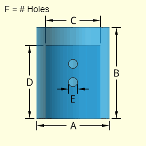
Outer Surface Area, Aouter, consists of the outer main cylinder, the top outside circular end, and the bottom edge. Subs tract the hole areas.
Aouter = Acylinder + Aend + Aedge end - Ahole ends
= (πA) B + (πA2/4) + π(A2-C2)/4 - F (πE2/4)
Inner Surface Area, Ainner, consists cylindrical inside surface and top circular end. Plus the inside cylindrical surface of the holes minus the end of the hole.
Ainner = Ainside cylinder + Ainside end
+ Ahole cylinder - Ahole end
= (πC) D + (πC2/4)
+ F (πE) (A-C)/2 - F (πE2/4)
ATotal = Aouter + Ainner
Volume, V, consists of the difference of the outside cylinder minus the hollow inside cylinder. Then subs tract all instances of the holes.
V = (πA2/4) B - (πC2/4) D - F (πE2/4) (A - C)/2
| Value | Equations | WE Program |
| Case 1 | ||
| Surface Area | 505.8 in2 | 505.8 in2 |
| Volume | 274.9 in3 | |
| Part Weight | 9.931 lb | 9.931 lb |
| Case 2 | ||
| Surface Area | 4,769 cm2 | 4,769 cm2 |
| Volume | 6,114 cm3 | |
| Part Weight | 13.48 lb | 13.48 lb |
| Case Number | ||
| Parameter | 1 | 2 |
| A | 8 in | 20 cm |
| B | 10 in | 40 cm |
| C | 6 in | 16 cm |
| D | 8 in | 32 cm |
| E | 1 in | 2 cm |
| F | 2 | 3 |
| test density |
1 gm/cm3 | 1 gm/cm3 |
Conversion Constants to
determine part weight in lb
1 gm/cm3 = 2.2046×10⁻⁶ lb/mm3
= 0.036127 lb/in3
The Cylinder with Holes object is a right constant cylindrical shape with four possible hole types.
The shape can have up to four different hole types. Not all four types must be used (just leave those input fields blank). Each hole type can have a different number of holes (N), depth (H), and diameter (D). Each hole type is labeled with its number after N, H and D, such as N2, H2 and D2. Number may also be a subscript.
The location of the holes is not needed for volume and surface area calculations. But it is assumed that the holes diameters are not large, and they will be contained inside the cylinder diameter, A. Also, it is assumed that a given hole depth does not exceed the cylinder diameter, A.
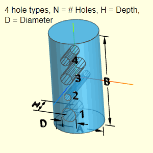
Outer Surface Area, Aouter, consists of the outer main cylinder, two circular ends, and subtraction of the holes (four possible types). Note, the equation ignores holes that pass all the way through. Only one end is subtracted.
Aouter = Acylinder + Aends - Ahole ends
= (πA) B + 2 (πA2/4)
- (πD12/4) N1 - (πD22/4) N2
- (πD32/4) N3 - (πD42/4) N4
Inner Surface Area, Ainner, consists of the hole cylindrical surface and one end. Note, the equation ignores holes that pass all the way through. One end is always added regardless.
Ainner = Ahole cylinders + Ahole ends
= (πD1) H1 N1 + (πD2) H2 N2
+ (πD3) H3 N3 + (πD4) H4 N4
+ (πD12/4) N1 + (πD22/4) N2
+ (πD32/4) N3 + (πD42/4) N4
ATotal = Aouter + Ainner
Volume, V, consists of the cylinder minus all four types of holes.
V = (πA2/4) B - (πD12/4) H1 N1 - (πD22/4) H2 N2
- (πD32/4) H3 N3 - (πD42/4) H4 N4
| CAUTION |
Calculations do NOT check if
|
| Value | Equations | WE Program |
| Case 1 | ||
| Surface Area | 93.82 in2 | 93.82 in2 |
| Volume | 39.59 in3 | |
| Part Weight | 1.430 lb | 1.430 lb |
| Case 2 | ||
| Surface Area | 11,820 mm2 | 11.820 mm2 |
| Volume | 35,563 mm3 | |
| Part Weight | 0.07840 lb | 0.07840 lb |
Conversion Constants to
determine part weight in lb
1 gm/cm3 = 2.2046×10⁻⁶ lb/mm3
= 0.036127 lb/in3
| Case Number | ||
| Parameter | 1 | 2 |
| A | 3 in | 45 mm |
| B | 6 in | 30 mm |
| D1 | 0.75 in | 6 mm |
| H1 | 1.5 in | 15 mm |
| N1 | 1 | 4 |
| D2 | 0.125 in | 4 mm |
| H2 | 3 in | 35 mm |
| N2 | 2 in | 1 mm |
| D3 | 0.5 in | 10 |
| H3 | 2 in | 5 mm |
| N3 | 5 | 3 |
| D4 | 0.325 in | 15 mm |
| H4 | 0.5 in | 25 mm |
| N4 | 3 | 2 |
| test density |
1 gm/cm3 | 1 gm/cm3 |
24 Nov 2020 - Kurt Gramoll
1) Equations were modified in the program to match the above equations. Previously, holes 3 and 4 doubled the volume and surface area due to an error using 0.5 constant instead of 0.25. Hole types 1 and 2 were correct.
2) Inner surface was modified to include one end surface for each hole. This was previously not included.
The Cylinder object is one of the more basic shapes. It is a constant cylindrical tube or rod. The height, B and diameter, A can be changed.
Technical Calculations
Outer Surface Area, Aouter, consists of both the curved cylindrical section and both circular ends.
Aouter = Acylinder + Aends
= (πA) B + 2(πA2/4)
Inner Surface Area, Ainner, does not exist.
Ainner = 0
ATotal = Aouter + Ainner
Volume, V, consists of a single cylinder.
V = (πA2/4) B

Calculation Caparison
| Value | Equations | WE Program |
| Case 1 | ||
| Surface Area | 70.69 in2 | 70.69 in2 |
| Volume | 42.41 in3 | |
| Part Weight | 1.532 lb | 1.532 lb |
| Case 2 | ||
| Surface Area | 3,181 mm2 | 3,181 mm2 |
| Volume | 47,710 mm3 | |
| Part Weight | 0.1052 lb | 0.1052 lb |
Input Values
| Case Number | ||
| Parameter | 1 | 2 |
| A | 3 in | 45 mm |
| B | 6 in | 30 mm |
| test density |
1 gm/cm3 | 1 gm/cm3 |
Conversion Constants to
determine part weight in lb
1 gm/cm3 = 2.2046×10⁻⁶ lb/mm3
= 0.036127 lb/in3
The Escapement Lever is a nonsymmetrical shape with various protrusions. The two long arms sticking out both have a single hole that goes through the arm thickness, F. There are two smaller arms near the center that has two parts each. Each of the two parts of the smaller inner arms are rectangular with width, height, and depth dimensions.
Technical Calculations
Outer Surface Area, Aouter, consists upper and lower trapezoidal arms with holes, center circular shape with hole, and projections on each side,
Aouter = Alevers + Acenter + Aprojections
= 2(C + A)B + 2F(B + A) + 2F[(A - C)2 + B2]0.5
- πI2 + 2π(G2 - H2) + πGF - 2CF
+ 4(JD + 2FD + EF + JF)
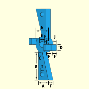
Inner Surface Area, Ainner, includes the inside surface of the three holes,
Ainner = 2IπF + HπF = πF(2I + H)
ATotal = Aouter + Ainner
Volume, V, consists upper and lower trapezoidal arms with holes, center circular shape with hole, and projections on each side,
V = Vlevers + Vcenter + Vprojections
= 2[(C + A)/2]BF + π(G2 - H2)F/4 - 2π I2F/4
+ 2JDF + 2EDF
= (C + A)BF + πF(G2 - H2 - 2I2)/4 + 2(J + E)DF
| Value | Equations | WE Program |
| Case 1 | ||
| Surface Area | 1,934 in2 | 1,934 in2 |
| Volume | 1,449 in3 | |
| Part Weight | 52.35 lb | 52.35 lb |
| Case 2 | ||
| Surface Area | 1,803 cm2 | 1,803 cm2 |
| Volume | 972.7 cm3 | |
| Part Weight | 2.145 lb | 2.145 lb |
Conversion Constants to
determine part weight in lb
1 gm/cm3 = 2.2046×10⁻⁶ lb/mm3
= 0.036127 lb/in3
| Case Number | ||
| Parameter | 1 | 2 |
| A | 8 in | 7 cm |
| B | 18 in | 16 cm |
| C | 3 in | 3 cm |
| D | 4 in | 5 cm |
| E | 2 in | 3 cm |
| F | 5 in | 3 cm |
| G | 10 in | 12 cm |
| H | 4 in | 4 cm |
| I | 3 in | 2 cm |
| J | 3 in | 4 cm |
| test density |
1 gm/cm3 | 1 gm/cm3 |
26 Dec 2020 - Kurt Gramoll
Volume equation was correct but surface equations incorrect.
1) Equation for inside surface (two holes) incorrectly included with outside surface
2) Upper and lower arms incorrectly modeled as rectangular shape, they are trapezoidal shape
3) Incorrectly added I hole surface instead of subtract
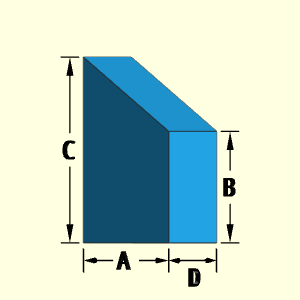
The Fin object is a solid inclined rectangular shape with one side higher than the other. The shape has four dimensions to describe its volume and surface.
Technical Calculations
Outer Surface Area, Aouter,
Aouter = 2A (C + B)/2 + BD + CD + AD
+ D [(C - B)2 + A 2]0.5
= A(C + B) + C(A + B + C) + D [(C - B)2 + A 2]0.5
Inner Surface Area, Ainner, does not exist.
Ainner = 0
ATotal = Aouter + Ainner
Volume, V, consists of a single cylinder.
V = AD (C + B)/2
| Value | Equations | WE Program |
| Case 1 | ||
| Surface Area | 53.21 in2 | 53.21 in2 |
| Volume | 24.00 in3 | |
| Part Weight | 0.8671 lb | 0.8671 lb |
| Case 2 | ||
| Surface Area | 222.2 cm2 | 222.2 cm2 |
| Volume | 208.0 cm3 | |
| Part Weight | 0.4586 lb | 0.4586 lb |
| Case Number | ||
| Parameter | 1 | 2 |
| A | 3 in | 8 cm |
| B | 3 in | 5 cm |
| C | 5 in | 8 cm |
| D | 2 in | 4 cm |
| test density |
1 gm/cm3 | 1 gm/cm3 |
Conversion Constants to
determine part weight in lb
1 gm/cm3 = 2.2046×10⁻⁶ lb/mm3
= 0.036127 lb/in3
The Firing Pin is a solid object consisting of two cylindrical sections and a small semispherical ball on top. The two cylindrical sections can have different heights and diameters. The top semispherical ball is mounted at the center of the top cylinder section. The ball diameter must be less than the top cylinder diameter.
Technical Calculations
Outer Surface Area, Aouter,
Aouter = πA2/4 + πAB + π(A2 - C2)/4
+ πDC + π(D2 - E2)/4 + (4/2) πE2/4
= π(A2/2 + AB + DC + D2/4 + E2/4)
Inner Surface Area, Ainner, does not exist.
Ainner = 0
ATotal = Aouter + Ainner
Volume, V, consists of a single cylinder.
V = πBA2/4 + πCD2/4 + (2/3) πE3/8
= π(BA2 + CD2 + E3/3)/4

| Value | Equations | WE Program |
| Case 1 | ||
| Surface Area | 716.3 in2 | 716.3 in2 |
| Volume | 1,171 in3 | |
| Part Weight | 42.30 lb | 42.30 lb |
| Case 2 | ||
| Surface Area | 361.3 cm2 | 361.3 cm2 |
| Volume | 385.4 cm3 | |
| Part Weight | 0.8496 lb | 0.8496 lb |
| Case Number | ||
| Parameter | 1 | 2 |
| A | 10 in | 6 cm |
| B | 12 in | 10 cm |
| C | 8 in | 8 cm |
| D | 6 in | 4 cm |
| E | 2 in | 2 cm |
| test density |
1 gm/cm3 | 1 gm/cm3 |
Conversion Constants to
determine part weight in lb
1 gm/cm3 = 2.2046×10⁻⁶ lb/mm3
= 0.036127 lb/in3
20 Dec 2020 - Kurt Gramoll
1) Previous surface equation excluded the top surface, D. Both volume and surface equations were simplified.
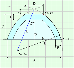
The Front Body shape has an ogive (a partial circular arc curve) top section with a flatten tip. The rate of curvature of the top section can be changed by modifying the radius dimension, B. The location of arc cure ('+' symbol) is determined by the program to match the other dimensions and D. The ogive curve does not have to be a vertical tangent at the bottom point (where A and C join).
It is possible to have a non-vertical tangent at the bottom edge (point at F and A).
The thickness is defined by the difference of A and E, and is constant in both curve sides and top flat tip.
The top vertical line at the joint does not technically exist. It is simply an artifact from the 3D modeling program.

The location of the arc center, the '+' symbol on diagram, is determined from the lower point of C and A dimension and the upper point of C and D dimension. Both these points are known.
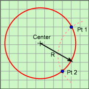
As illustrated in the circle diagram, two points and the radius can define an arc curve without needing other dimensions. There is a second possible circular arc (dashed line), but it is not realistic so is not considered for this shape.
Technical Calculations
The Front Body shape is similar to the top section of the Projectile shape but has the top point removed and replaced with a solid circular disk. Also, the Front Body is hollow like the Hollow Projectile body.
First, the ogive curve needs to be modeled as an equation. Then it can be revolved around a given line to create the solid. Recall, an ogive curve is a section of a circular arc as mentioned in projectile shape section. The ogive needs to be described as an equation in an x-y cartesian coordinate system so it can be integrated about the x-axis to generate a solid using the infinitesimal slice dx.
The diagram at the right shows a general ogive curve (red line) that describes the edge of the front body. The curve starts at the x-y coordinate origin even though the shape will start a distance 'g' from the origin. That curve is rotated about the x-axis giving the outside Front Body shape. The final curve equation is (see Solid Projectile for derivation details - note dimension letters may be different),
y = [B2 - (x - B cosα)2]0.5 - B sinα
where α = cos-1[ (R2 + L2)0.5 / (2B) ] - tan-1(R/L)
This form is important so that the curve can be rotated about the x-axis to give a solid. The parameters A, B, and C are the input variables in the Weight Estimator program. Parameter g will be defined later, but can be considered as an given value. Parameter D will be used when integrating the ogive curve.
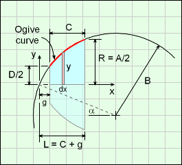
Before integration can be done to find the volume and surface area of a truncated ogive curve about an axis, the distance, 'g' needs to be defined. The distance g can be determined using the other dimensions A, B, C,and D.
First, the location of xo, yo (center of circular arc for outside surface) needs to be determined. This point will also be used in other calculations. Note, the coordinate system is different in this diagram used to find xo, yo.
Knowing two points on a circular arc (points 1 and 2 in diagram), and the radius of the arc, B, the center point location can be determined (derivation not given here, basic geometry exercise). Points 1 and 2 are,
(x1, y1) = (A/2, 0)
(x2, y2) = (D/2, C)
then
xo = (D + A)/4 - (C/2) (b / a)
yo = (C/2) + [(D - A)/4)] (b / a)
where a = [(D - A)2/16 + C2/4]0.5
b = [B2 - (D - A)2/16 - C2/4]0.5
This gives 'g' distance as,
g = B cosα - C + yo
Note, yo can be ether positive or negative, depending on the location of point o.
With xo known, angle α can be defined as
α = sin-1(xo / B)
Note, α can be negative, depends on the sign of xo.
Using distance 'g', the ogive curve can now be rotated about its center axis as shown in the first diagram (diagram with red ogive curve). Using the ogive curve, the volume can be calculated by considering a series of disks, and integrating them the from g to L (= C + g),

For simplification, let a1 = B cosα and b1 = B sinα. Completing the integration using math tables (steps not shown) gives,
V = h(x = C+g) - h(x= g)
where h(x) = π [(B2 + b12 - a12) x + a1 x2 - x3/3]
+ π b1 { (x - a1) [B2 - (x - a1)2]0.5
+ B2 sin-1[ (x - a1)/B] }
This equation is similar to the volume equation for projectile shapes except this starts at g instead of 0.
Similarly, the surface can be determined by integrating the circumference of the element dx. The slope distance is included (square root term), giving
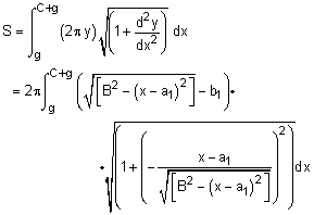
where a1 = B cosα and b1 = B sinα. While this looks messy, using basic algebra, it actually simplifies to

Completing the integration using math tables (steps not shown) gives,
S = 2πB [ (C+g) + b1 sin-1[(a1 - (C+g)) / B]
- 2πB [ g + b1 sin-1[(a1 - g) / B]
= 2πB [C + b1 sin-1[(a1 - C - g) / B]
- b1 sin-1[(a1 - g) / B]
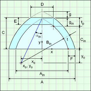
For the inside ogive, two points on the curve are needed, just like the outside curve. These two point will be referred to as the top and bottom points as noted in the diagram. To determine the top point, the shell thickness, t, and the top vertical thickness, tp, are needed. From the diagram
sinβ = yo/B
and
cosβ = t / F
Square both equations and add,
t = [1 + (yo/B)2]0.5
The t and tp thickness are related, (see Oval shape for derivation details),
tp = (2B/A) t
So the two points are,
(xtop, ytop) = (D/2, C - tp)
(xbottom, ybottom) = (D/2, C - tp)
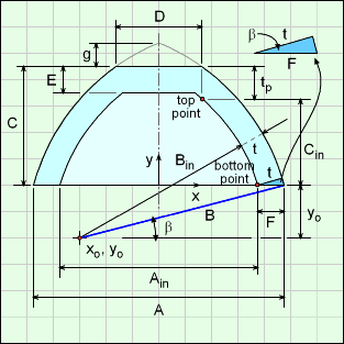
Finally, the integration equations for the inside volume and surface (see above) need Ain, Bin, Cin and gin for the inside ogive curve.
Ain = A - 2F
Bin = B - t
= B - F [1 + (yo/B)2]0.5
Cin = C - tp
gin = Bin cosαin - Cin + yo
where αin = sin-1(xo / Bin)
and a1-in = Bin cosαin and b1-in = Bin sinαin.
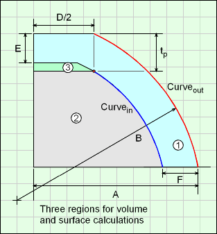
For the final volume and surface equations, it is best to split the shape into three regions, 1, 2 and 3 as shown in the diagram. These regions are also referred to as out, in and tapered cylinder regions, respectively. Region 1 includes region 2 and 3 (2 and 3 overlap region 1).
Volume, V, total for the full Front Body is
V = Vout - Vin - Vtapered cylinder
if E <= tp. The last term is positive if E > tp
Due to the large number of terms in this equation, they are not shown. In Weight Estimator code functions are used for each volume. See code for details.
Outer Surface Area, Aouter, includes the outer ogive surface plus the top and bottom edges.
Aouter = 2πB [C + b1 sin-1[(a1 - C - g) / B]
- b1 sin-1[(a1 - g) / B]
+ π(D/2)2 + π[(A/2)2 - (A/2 - F)2]
Inner Surface Area, Ainner, includes the inner ogive surface plus an approximate tamper cylinder above the inside ogive curve,
Ainner = Ainner ogive - Vtapered cylinder
Ainner= 2πBin [Cin + b1 sin-1[(a1 - C - gin) / Bin]
- b1 sin-1[(a1 - gin) / Bin]
+ π (D/2 - tp + E)2
+ π(D - tp + E) 20.5(tp - E)
ATotal = Aouter + Ainner
| Value | Equations | WE Program |
| Case 1 | ||
| Surface Area | 536.5 in2 | 536.5 in2 |
| Part Weight | 10.69 lb | 10.69 lb |
| Case 2 | ||
| Surface Area | 2,241 cm2 | 2,241 cm2 |
| Part Weight | 6.335 lb | 6.335 lb |
Conversion Constants to
determine part weight in lb
1 gm/cm3 = 2.2046×10⁻⁶ lb/mm3
= 0.036127 lb/in3
| Case Number | ||
| Parameter | 1 | 2 |
| A | 10 in | 30 cm |
| B | 20 in | 20.6 cm |
| C | 12 in | 13 cm |
| D | 3 in | 10 cm |
| E | 1 in | 2 cm |
| F | 1 in | 3 cm |
| test density |
1 gm/cm3 | 1 gm/cm3 |
29 Dec 2020 - Kurt Gramoll
1) Previous equations were convoluted and could not be verified. New equations were derived. New equations match the old equations within 5%.
The Fuze Adapter object consists of a truncated conical top section and a solid cylindrical bottom section. The top section has an internal hollow cylindrical hole through its total depth. This hole does not go through the bottom cylinder section.
Technical Calculations
Outer Surface Area, Aouter,
Aouter = π [(E+A)/2] [(A/2 - E/2)2 +D2 ]
+ π(E2 - F2) /4 + π(A2 - B2) /4 + πBC + π B2/4
Inner Surface Area, Ainner,
Ainner = π FD + π F2/4
ATotal = Aouter + Ainner
Volume, V, consists of a single cylinder.
V = πD(E2 + A2 + AE) /12 + πB2C /4 - πF2D /4

| Value | Equations | WE Program |
| Case 1 | ||
| Surface Area | 623.5 in2 | 623.5 in2 |
| Volume | 820.7 in3 | |
| Part Weight | 29.65 lb | 29.65 lb |
| Case 2 | ||
| Surface Area | 440.2 cm2 | 440.2 cm2 |
| Volume | 459.2 cm3 | |
| Part Weight | 1.0123 lb | 1.0124 lb |
| Case Number | ||
| Parameter | 1 | 2 |
| A | 15 in | 10 cm |
| B | 5 in | 5 cm |
| C | 5 in | 6 cm |
| D | 10 in | 8 cm |
| E | 3 in | 5 cm |
| F | 1 in | 2 cm |
| test density |
1 gm/cm3 | 1 gm/cm3 |
Conversion Constants to
determine part weight in lb
1 gm/cm3 = 2.2046×10⁻⁶ lb/mm3
= 0.036127 lb/in3
The Gear object is a basic gear shape. The gear teeth size can be changed, both depth and width. Also, the number of teeth can be modified. The program does not check if the teeth intercept each other if too many teeth or if the teeth are too big. The user should visually check and confirm that the shape is realistic and acceptable. The internal hole diameter can also be changed.
Technical Calculations
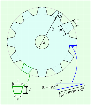
To simplify the volume and surface calculations, the gear teeth are modeled as trapezoid even though the top and bottom edges are slightly curved. .
Outer Surface Area, Aouter, includes two main surfaces, top/bottom and outer edge. The top and bottom are identical,
Atop/bottom = 2 [π(A/2 + B)2 - πA2/4 + (F/2 + E/2)CG]

The edge has three surfaces, end of the teeth, sides of the teeth, and gap between teeth. The diagram shows the dimensions of the teeth.
Aouter edge= Aend + Aside + Agap
= FDG + [(E/2 - F/2)2+ C2]0.5 D2G
+ [(A + 2B)π - GE] D
Note, the gap was calculated by taking the full circle perimeter at the gap, and subtracted the tooth root length, E.
Combining surfaces, gives
Aouter = Atop/bottom + Aouter edge
= 2 [π(A/2 + B)2 - πA2/4 + (F/2 + E/2)CG]
+ FDG + [(E/2 - F/2)2+ C2]0.5 D2G
+ [(A + 2B)π - GE] D
Inner Surface Area, Ainner, is just the inside ring,
Ainner = π FD + π F2/4
ATotal = Aouter + Ainner
Volume, V, is the top or bottom surface, multiplied by the gear thickness,
V = = D [π(A/2 + B)2 - πA2/4 + (F/2 + E/2)CG]
| Value | Equations | WE Program |
| Case 1 | ||
| Surface Area | 1702 in2 | 1702 in2 |
| Volume | 2,112 in3 | |
| Part Weight | 76.32 lb | 76.32 lb |
| Case 2 | ||
| Surface Area | 828.2 cm2 | 828.2 cm2 |
| Volume | 564.4 cm3 | |
| Part Weight | 1.244 lb | 1.244 lb |
| Case Number | ||
| Parameter | 1 | 2 |
| A | 8 in | 6 cm |
| B | 8 in | 6 cm |
| C | 3 in | 2 cm |
| D | 4 in | 2 cm |
| E | 4 in | 2 cm |
| F | 3 in | 1.5 cm |
| G | 12 | 16 |
| test density |
1 gm/cm3 | 1 gm/cm3 |
Conversion Constants to
determine part weight in lb
1 gm/cm3 = 2.2046×10⁻⁶ lb/mm3
= 0.036127 lb/in3
22 Dec 2020 - Kurt Gramoll
1) Previous equations were convoluted and could not be verified. New equations were derived. New equations match the old equations within 0.1%.
The Head object is basically a truncated conical section for the top, a middle cylinder and a cylindrical section for the bottom. The bottom cylindrical section has two internal hollow shapes, a cylinder and a cone.
Outer Surface Area, Aouter, is based on the top tampered cylinder, middle cylinder and bottom cylinder.
Aouter = A tapered cyl + A middle cyl + A bottom cyl
= π (F/2 + G/2) [ (G/2 - F/2)2 + E2 ]0.5
+ πF2/4 + π(G2 - H2)/4 + πHD
+ π(A2 - H2)/4 + π(B + C) + π(A2 - I2)/4

Inner Surface Area, Ainner, is the inside hollow cone and cylinder,
Ainner = π (I/2) [ (I/2)2 + C2) ]0.5 + π I B
ATotal = Aouter + Ainner
Volume, V, involves the three main shapes and subtracting the two inside hollow shapes,
V = Vtapered cyl + V2 cyl - Vhollow cone and cyl
= π E (F2 + G2 + FG) /12 +
π H2D /4
+
π A2(C + B)/4 -
π I2B /4 -
π I2C /12
| CAUTION |
Calculations do NOT check if
|
| Value | Equations | WE Program |
| Case 1 | ||
| Surface Area | 1,501 in2 | 1,501 in2 |
| Volume | 2,473 in3 | |
| Part Weight | 89.36 lb | 89.36 lb |
| Case 2 | ||
| Surface Area | 1,893 cm2 | 1,893 cm2 |
| Volume | 3,412 cm3 | |
| Part Weight | 7.522 lb | 7.522 lb |
| Case Number | ||
| Parameter | 1 | 2 |
| A | 10 in | 12 cm |
| B | 4 in | 6 cm |
| C | 6 in | 8 cm |
| D | 2 in | 4 cm |
| E | 10 in | 12 cm |
| F | 6 in | 8 cm |
| G | 22 in | 20 cm |
| H | 6 in | 6 cm |
| I | 4 in | 6 cm |
| test density |
1 gm/cm3 | 1 gm/cm3 |
Conversion Constants to
determine part weight in lb
1 gm/cm3 = 2.2046×10⁻⁶ lb/mm3
= 0.036127 lb/in3
22 Dec 2020 - Kurt Gramoll
1) Previous equations did not separate inside and outside surfaces. The new equations have both the inside and outside surface areas. All equations were rearranged to match the equation format given in the help page.
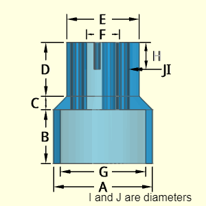
The Housing object is one of the more complex shapes. Its basic shape consists of a top and bottom hollow cylinder and a conical transition section. The top cylindrical and conical section have the same internal radius, F. The lower cylindrical section has a separate internal radius, G.
The top section has two types of holes at different depths. The J holes (total of 3) has a depth equal to D plus C. The I holes (total of 3) has a depth that can be set by the user. Both hole types can have different diameters. But the 3 holes in either hole type will have the same diameter. I and J are the diameters of their respective holes.
Outer Surface Area, Aouter, is based on the top cylinder, middle tampered cylinder and bottom cylinder. To and bottom surface are included. Hole areas need to be subtracted The I hole ends needs to be subtracted from Aouter using an if statement in code.
Aouter = Atop cyl + Atapered cyl + Abot cyl - Ahole ends
= π(E2 - F2)/4 + πED
+ π (E/2 + A/2) [ (E/2 - A/2)2 + C2 ]0.5
+ πAB + π(A2 - G2)/4 - 3π(J2 + I2)/4
Inner Surface Area, Ainner, is the inside is two hollow cylinders, and surface between the two inside cylinders, The I hole end needs to be subtracted from Ainner using an if statement in code.
Ainner =
πF(D + C) + π(G2 - F2)/4 + πGB
+ 3 πJ(D+C) + 3π IH - 3πJ2/4
ATotal = Aouter + Ainner
Volume, V, is based on the top cylinder, middle tampered cylinder and bottom cylinder. Inside hollow cylinders are subtracted.
V = Vtapered cyl + V2 cyl - Vhollow cone and cyl
= πE2D /4 + πA2B /4 + πC(A2 + E2 + AE) /12
- πG2B /4 - πF2(D + C) /4
- 3πJ2(D + C) /4 -
3π I2H /4
| CAUTION |
Calculations do NOT check if
|
| Value | Equations | WE Program |
| Case 1 | ||
| Surface Area | 1,690 in2 | 1,690 in2 |
| Volume | 1080 in3 | |
| Part Weight | 39.01 lb | 39.01 lb |
| Case 2 | ||
| Surface Area | 2,323 cm2 | 2,323 cm2 |
| Volume | 2991 cm3 | |
| Part Weight | 6.594 lb | 6.594 lb |
| Case Number | ||
| Parameter | 1 | 2 |
| A | 15 in | 20 cm |
| B | 8 in | 10 cm |
| C | 2 in | 2 cm |
| D | 8 in | 6 cm |
| E | 11 in | 14 cm |
| F | 5 in | 5 cm |
| G | 13 in | 12 cm |
| H | 4 in | 8 cm |
| I (3) | 1 in | 2 cm |
| J (3) | 2 in | 3 cm |
| test density |
1 gm/cm3 | 1 gm/cm3 |
Conversion Constants to
determine part weight in lb
1 gm/cm3 = 2.2046×10⁻⁶ lb/mm3
= 0.036127 lb/in3
23 Dec 2020 - Kurt Gramoll
Various problems with original equations,
1) Volume is missing top center hole going through section C, corrected
1) Missing J hole end for inside
1) Missing inside surface
1) Result page has wrong J value (used I => _HoursingResult.cshtml page corrected)
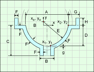
The Lower Body represents a circular rotated shape similar to a circular sink bowl with a drain. The curvature of the side is defined by 2 points, G and A, and D and B, plus the radius length E. But the location of the radius center (the "+" symbol in the diagram) is not known, and must be determined by the program.
It is assumed that the thickness F is constant at all location.

The location of the arc center, the '+' symbol on diagram, is determined from the lower point of D and B dimension and the upper point of A and D dimension. Both these points are known.
As illustrated in the circle diagram, two points and the radius can define an arc curve without needing other dimensions. There is a second possible circular arc (dashed line), but it is not realistic so is not considered for this shape.

Technical Calculations
The Lower Body shape is similar to the top section of the Projectile shape but has the top point removed and is flipped vertically. Also, the Lower Body is hollow like the Hollow Projectile body. There are also various cylinders and disks attached to top and bottom (all have thickness of F.
First, the ogive curve section needs to be modeled as an equation. Then it can be revolved around a given line to create the solid. Recall, an ogive curve is a section of a circular arc as mentioned in projectile shape section. The ogive needs to be described as an equation in an x-y cartesian coordinate system so it can be integrated about the x-axis to generate a solid using the infinitesimal slice dx.
The diagram at the right shows a general ogive curve (red line) that describes the edge of the front body. The curve starts at the x-y coordinate origin even though the shape will start a distance 'g' from the origin. That curve is rotated about the x-axis giving the outside and inside Lower Body curved shape. The final curve equation is (see Solid Projectile for derivation details - note dimension letters may be different),
y = [E2 - (x - E cosα)2]0.5 - E sinα
where α = cos-1[ (R2 + L2)0.5 / (2E) ] - tan-1(R/L)
This form is important so that the curve can be rotated about the x-axis to give a solid. The parameters A, D, and E are the input variables in the Weight Estimator program. Parameter g will be defined later, but can be considered as an given value. Parameter B will be used when integrating the ogive curve.
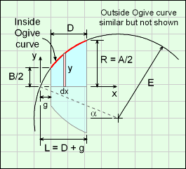
Before integration can be done to find the volume and surface area of a truncated ogive curve about an axis, the distance, 'g' needs to be defined. The distance g can be determined using the other dimensions A, B, C,and D.
First, the location of xo, yo (center of circular arc for outside surface) needs to be determined. This point will also be used in other calculations. Note, the coordinate system is different in this diagram used to find xo, yo.
Knowing two points on a circular arc (points 1 and 2 in diagram), and the radius of the arc, E, the center point location can be determined (derivation not given here, basic geometry exercise). Points 1 and 2 are,
(x1, y1) = (B/2, -D)
(x2, y2) = (A/2, 0)
then
xo = (A + B)/4 - (D/2) (b / a)
yo = -D/2 + [(A - B)/4)] (b / a)
where a = [(A - B)2/16 + D2/4]0.5
b = [E2 - (A - B)2/16 - D2/4]0.5
This gives 'gi' distance as,
gi = E cosαi - D - yo
Note, yo can be ether positive or negative, depending on the location of point o.
With xo known, angle αi can be defined as
αi = sin-1(xo / E)
Note, αi can be negative, depends on the sign of xo.
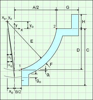
Using distance 'g' (gi for inside curve and go for outside curve), the ogive curve can now be rotated about its center axis as shown in the first diagram (diagram with red ogive curve). Using the ogive curve, the volume can be calculated by considering a series of disks, and integrating them the from g to L (= D + g),

For simplification, let a1 = E cosα and b1 = E sinα. Completing the integration using math tables (steps not shown) gives,
V = h(x = D+g) - h(x= g)
where h(x) = π [(E2 + b12 - a12) x + a1 x2 - x3/3]
+ π b1 { (x - a1) [E2 - (x - a1)2]0.5
+ E2 sin-1[ (x - a1)/E] }
This equation is similar to the volume equation for projectile shapes except this starts at g instead of 0. This equation can be used for either the inside or outside ogive curve.
Similarly, the surface can be determined by integrating the circumference of the element dx. The slope distance is included (square root term), giving
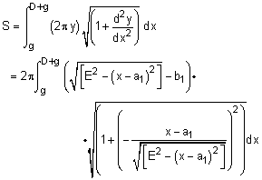
where a1 = E cosα and b1 = E sinα. While this looks messy, using basic algebra, it actually simplifies to

Completing the integration using math tables (steps not shown) gives,
S = 2πE [ (D+g) + b1 sin-1[(a1 - (D+g)) / E]
- 2πE [ g + b1 sin-1[(a1 - g) / E]
= 2πE [D + b1 sin-1[(a1 - D - g) / E]
- b1 sin-1[(a1 - g) / E]
For the outside ogive, two points (3 and 4) on the curve are needed, just like the inside curve. These two point are noted as 3 and 4 in the diagram. With these points, Eo, go, and p can be determined, and used in the integration equation developed previously.
Eo = E + F
go = Eo [cos(αo) - cos(βo)]
where αo = sin-1(xo / Eo)
and βo = sin-1[(-xo + B/2 + F) / Eo]
p = Eo cosαo - F - yo
The volume and surface integration equations are from go to p. Note, the integration equation constants are now a1 = Eo cosαo and b1 = Eo sinαo.
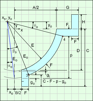
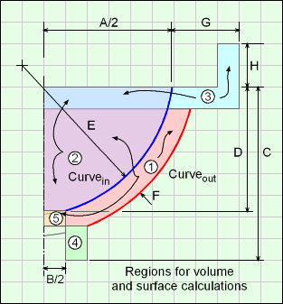
For the final volume and surface equations, it is best to split the shape into three regions, 1, 2 and 3 as shown in the diagram. These regions are also referred to as out, in and tapered cylinder regions, respectively. Region 1 includes region 2 and 3 (2 and 3 overlap region 1).
Volume, V, total for the full Lower Body is
V = V1 - V2 + V3 + V4 - V5
Due to the large number of terms in this equation, they are not shown. In Weight Estimator code functions are used for each volume. See code for details.
Outer Surface Area, Aouter, includes the outer ogive surface plus the flat outside surfaces. Note the top angle theta is used to locate the horizontal location of point 4,
Aouter = π [(A/2 + G)2 - (A/2 + G - F)2]
+ π [(B / 2 + F)2 - (B / 2)2]
+ π (A + 2 G) (H + F)
+ π (B + 2 F) (C - F - p + go)
+ π [(A/2 + G)2 - (Eo cosθo + xo)2]
+ 2π E (p - go + b1 sin-1[(a1 - p) /Eo]
- b1 sin-1[(a1 - go) /Eo)]
Inner Surface Area, Ainner, includes the inner ogive surface plus inside flat surfaces,
Ainner = π (A + 2 * G - 2 * F) H
+ π [(A/2 + G - F)2 - (A/2)2]
+ π B (C - D)
+ 2π E (D + b1 sin-1[(a1 - gi - D) / E]
- b1 sin-1[(a1 - gi) / E]
ATotal = Aouter + Ainner
| Value | Equations | WE Program |
| Case 1 | ||
| Surface Area | 2,483 in2 | 2,483 in2 |
| Part Weight | 42.61 lb | 42.61 lb |
| Case 2 | ||
| Surface Area | 6,168 cm2 | 6,168 cm2 |
| Part Weight | 18.44 lb | 18.44 lb |
Conversion Constants to
determine part weight in lb
1 gm/cm3 = 2.2046×10⁻⁶ lb/mm3
= 0.036127 lb/in3
| Case Number | ||
| Parameter | 1 | 2 |
| A | 20 in | 34 cm |
| B | 4 in | 6 cm |
| C | 18 in | 22 cm |
| D | 14 in | 14.7 cm |
| E | 18 in | 20.7 cm |
| F | 1 in | 3 cm |
| G | 4 in | 7 cm |
| H | 1 in | 2 cm |
| test density |
1 gm/cm3 | 1 gm/cm3 |
4 Jan 2021 - Kurt Gramoll
1) Previous equations were convoluted and could not be verified. New equations were derived. New equations match the old equations within 5% using graphical methods.
The Nut shape is a basic hexagon shape that is extruded a distance B. There is a hollow hole at the center with radius C. The diameter, A, is the distance from one flat side to the opposite side. A is not the length of a single side.
Technical Calculations
Outer Surface Area, Aouter,
Aouter = 30.5A2 + 30.52AB - πC2/2
Inner Surface Area, Ainner,
Ainner = πCB
ATotal = Aouter + Ainner
Volume, V, consists of a single sphere.
V = (30.5/2) A2B - π C2B/4

| Value | Equations | WE Program |
| Case 1 | ||
| Surface Area | 108.6 in2 | 108.6 in2 |
| Volume | 48.22 in3 | |
| Part Weight | 1.742 lb | 1.742 lb |
| Case 2 | ||
| Surface Area | 27.55 cm2 | 27.55 cm2 |
| Volume | 7.009 cm3 | |
| Part Weight | 0.01545 lb | 0.01545 lb |
| Case Number | ||
| Parameter | 1 | 2 |
| A | 6 in | 3 cm |
| B | 2 in | 1 cm |
| C | 3 in | 1 cm |
| test density |
1 gm/cm3 | 1 gm/cm3 |
Conversion Constants to
determine part weight in lb
1 gm/cm3 = 2.2046×10⁻⁶ lb/mm3
= 0.036127 lb/in3
17 Dec 2020 - Kurt Gramoll
1) Previous equations excluded the bottom (or top) surface. Both volume and surface equations were simplified.
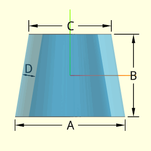
It should be noted, this shape is technically not based on an Ogive curve but has been given this name regardless. The shape is basically a tapered circular tube. The rate of taper and thickness can be set. The thickness is perpendicular to the side and is constant.
Technical Calculations
Volume, V
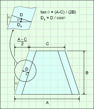
The volume is simply the outside tapered cylinder minus the inside tapered cylinder. The input value D is NOT the horizontal distance. The horizontal wall thickness, Dx, can be determined with trigonometry,
tanθ = (A - C) / (2B)
Dx = D / cosθ
Using the wall thickness, Dx, the volume is,
V = (π/12) B (A2 + C2 + A C)
- (π/12) B [(A - 2Dx)2 + (C - 2Dx)2
+ (A - 2Dx) (C - 2Dx))]
Outer Surface Area, Aouter,
The outer surface consists of the outside side surface and the top and bottom edge. The outside surface equation was developed in the Ogive solid shape (next section below) and can be used here. The top and bottom edge surfaces are simple circular surfaces,
Aoutside = π (A/2 + C/2) [ (A/2 - C/2)2 + B2 ]0.5
Aedges = (π/4) [A2 - (A - 2Dx)2 + C2 - (C - 2Dx)2 ]
Aouter = Aoutside + Aedges
Inner Surface Area, Ainner,
The inner surface is just a smaller tapered cylinder. The same surface equation can be used for the sloped surface with the horizontal wall thickness, Dx, included,
Ainner = (π/2) (A + C - 4 Dx) [ (A/2 - C/2)2 + B2 ]0.5
ATotal = Aouter + Ainner
| Value | Equations | WE Program |
| Case 1 | ||
| Surface Area | 266.9 in2 | 266.9 in2 |
| Volume | 114.4 in3 | |
| Part Weight | 4.133 lb | 4.133 lb |
| Case 2 | ||
| Surface Area | 1,056 cm2 | 1,056 cm2 |
| Volume | 479.9 cm3 | |
| Part Weight | 1.058 lb | 1.058 lb |
| Case Number | ||
| Parameter | 1 | 2 |
| A | 8 in | 14 cm |
| B | 6 in | 10 cm |
| C | 6 in | 18 cm |
| D | 1 in | 1 cm |
| test density |
1 gm/cm3 | 1 gm/cm3 |
Conversion Constants to
determine part weight in lb
1 gm/cm3 = 2.2046×10⁻⁶ lb/mm3
= 0.036127 lb/in3
It should be noted, this shape is technically not based on an Ogive curve but has been given this name regardless. The shape is basically a solid tapered cylindrical object. The rate of taper can be set with the upper and lower radius.
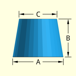
Technical Calculations
Volume, V
The simplest way to calculate the volume of a tapered cylinder is to consider a cone with the top cut off. Simply subtract the top cone from the full cone, and what remains is a tapered cylinder. So, using the volume equation for a cone the volume will be,
V = Vfull cone - Vtop cone
= (π/3) (A/2)2 h - (π/3) (A/2)2 (h - B)
= π [h(A2 - C2) + C2 B ] /12
The dimension h can be written in terms of A, B, and C giving h = B A / (A - C). Substitute and simplify,
V = π [ A B (A2 - C2) / (A - C) + B C2] /12
This can be rearranged, and simplified,
V = π B [ A (A + C) (A - C) / (A - C) + C2] /12
V = π B (A2 + C2 + A C) /12
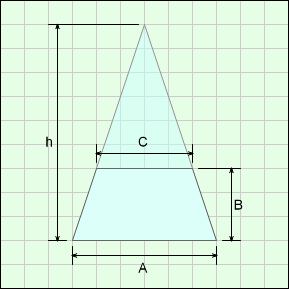
Outer Surface Area, Aouter,
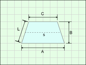
The side surface can be calculated as the slope length times the average circumference. It could also be integrated, but that would be more complex. The top and bottom circular surfaces also need to be included,
L = [(A/2 - C/2)2 + B2]
s = (A + C) / 2
Aouter = π (A/2 + C/2) [ (A/2 - C/2)2 + B2 ]0.5
+ π [(A/2)2 + (C/2)2]
Inner Surface Area, Ainner, does not exist.
Ainner = 0
ATotal = Aouter + Ainner
| Value | Equations | WE Program |
| Case 1 | ||
| Surface Area | 53.08 in2 | 53.08 in2 |
| Volume | 29.06 in3 | |
| Part Weight | 1.050 lb | 1.050 lb |
| Case 2 | ||
| Surface Area | 299.5 cm2 | 299.5 cm2 |
| Volume | 387.5 cm3 | |
| Part Weight | 0.8542 lb | 0.8542 lb |
| Case Number | ||
| Parameter | 1 | 2 |
| A | 4 in | 6 cm |
| B | 3 in | 10 cm |
| C | 3 in | 8 cm |
| test density |
1 gm/cm3 | 1 gm/cm3 |
Conversion Constants to
determine part weight in lb
1 gm/cm3 = 2.2046×10⁻⁶ lb/mm3
= 0.036127 lb/in3
10 Dec 2020 - Kurt Gramoll
1) Equations were modified in the program to match the above equations. Previously, the calculations used formulation that gave incorrect values if C > A, or if C = A. Now there are one set of equations.
The Oval shape is a circular arc rotated about a center line. If the arc length B is equal to half of A, then a sphere would be generated. The thickness can be set, and it is assumed to be constant.
The top and bottom vertical lines at the joint do not technically exist. They are simply an artifact from the 3D modeling program.
The dimension B is for the arc length from the arc circular center ('+' location) to the outside surface.
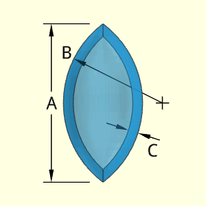
Technical Calculations
The hollow Oval consists of an outer and inner oval shape. Both ovals are similar but with different A and B variables, shown in the diagram as Ain and Bin.
The new Bin variable is simply the B minus the shell thickness, C. Giving,
Bin = B - C
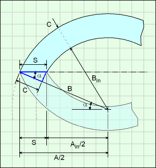
However, the inside oval Ain variable is not simply A minus C. The change in length of the oval depends on the angle a, as shown in the diagram. The angle can be calculated as,
cosα = (A/2) / B
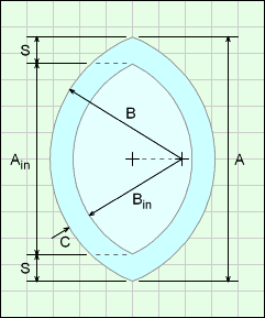
Using trigonometry equations on the blue triangle, the change in the shape length for one end is
cosα = C / S
This is not exact since the angle α is based on the outside oval, and should be based on the inside oval. But the inside oval is not yet know since S is unknown. Using the outside oval is extremely close, and is used here.
Combining the two equations gives,
S = (2B/A) C
So the new Ain variable is,
Ain = A - 2C
The volume and surface equation were derived in the solid oval section below, and will not be repeated here. The final equations are,
V = π [ (B2 A - A3 /12
- B2 [4B2 - A2]0.5 sin-1[A / (2B)]
and
Areaout = 2πBA - 2π [4B2 - A2]0.5 sin-1[A / (2B)]
Areain = 2πBinAin
- 2π [4Bin2 - Ain2]0.5 sin-1[Ain / (2Bin)]
| Value | Equations | WE Program |
| Case 1 | ||
| Surface Area | 1,229 in2 | 1,229 in2 |
| Volume | 603.6 in3 | |
| Part Weight | 21.81 lb | 21.81 lb |
| Case 2 | ||
| Surface Area | 498.6 cm2 | 498.6 cm2 |
| Volume | 236.5 cm3 | |
| Part Weight | 0.5215 lb | 0.5215 lb |
| Case Number | ||
| Parameter | 1 | 2 |
| A | 19 in | 16 cm |
| B | 10 in | 10 cm |
| C | 1 in | 1 cm |
| test density |
1 gm/cm3 | 1 gm/cm3 |
Conversion Constants to
determine part weight in lb
1 gm/cm3 = 2.2046×10⁻⁶ lb/mm3
= 0.036127 lb/in3
11 Dec 2020 - Kurt Gramoll
1) Equations were modified in the program to match the above equations. Previously, the calculations used the incorrect value (A-C) for the inside oval length, A. On the examples, this cause errors of 5-20%
The Oval shape is a circular arc rotated about a center line. If the arc length B is equal to half of A, then a sphere would be generated. This shape is a solid.
The dimension B is for the arc length from the arc circular center ('+' location) to the outside surface.

Technical Calculations
The shape is a simplification of the solid projectile shape. A circular arc (also called an ogive curve) is rotated about an arbitrary axis as shown in the diagram. The axis generally will not go through the center of curvature. The resulting shape is similar to a football (US), but not exactly (footballs are actually a prolate spheroid).
Since the shape is symmetrical about both axis, only one half of the curve will be used to calculate the volume and surface. Then the result will be doubled.
The input variables are only A (length from tip to tip) and B (radius of curvature for arc). Since the radius of curvature pivot point is at the centerline, the width of the shape can be determined from A and B
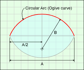
First, the ogive curve needs to be established. Then it can be revolved to create the solid. Recall, an ogive curve is a section of a circular arc as mentioned in introduction section above. The ogive needs to be described as an equation in an x-y cartesian coordinate system so it can be used in math equations to generate a solid.
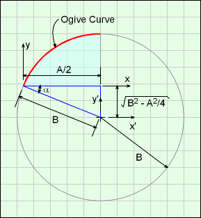
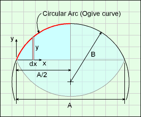
The diagram at the right shows the ogive curve (red line) that describes the edge of the upper section of the oval. That curve is rotated about the x-axis giving half shape. The lower half shape is identical, so only the upper half is derived.
The ogive curve can then be modeled as a section of a circle the x'-y' coordinate system,
x'2 + y'2 = D2
Next, t he x'-y' coordinate system can be translated into the x-y coordinate system. Using Pythagoras' theorem on the blue triangle for translation distances,
(x - A/2)2 + (y + [B2 - A2/4]0.5 )2 = B2
Rearranging gives,
y = [B2 - (x - A/2)2]0.5 - [B2 - A2/4]0.5
This form is important so that the curve can be rotated about the x-axis to give a solid. The parameters A and B are the input variables in the Weight Estimator program.
Using the ogive curve, the volume can be calculated by considering a series of disks, and integrating them the length of projectile, C,

For simplification, let b1 = [B2 - A2/4]0.5. Rearranging the integration terms,
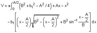
Completing the integration using math tables (steps not shown) gives,
V = π [ (B2 A - A3 /12 - B2 [4B2 - A2]0.5 sin-1[A/(2B)]
The above equation was doubled to give volume for both halfs.
Similarly, the surface can be determined by integrating the circumference of the element dx. The slope distance is included (square root term), giving
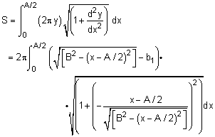
where b1 = [B2 - A2/4]0.5. While this looks messy, using basic algebra, it actually simplifies to

Completing the integration using math tables (steps not shown) gives,
S = 2πBA - 2π [4B2 - A2]0.5 sin-1[A / (2B)]
| Value | Equations | WE Program |
| Case 1 | ||
| Surface Area | 702.1 in2 | 702.1 in2 |
| Volume | 1,715 in3 | |
| Part Weight | 61.94 lb | 61.94 lb |
| Case 2 | ||
| Surface Area | 306.1 cm2 | 306.1 cm2 |
| Volume | 458.4 cm3 | |
| Part Weight | 1.011 lb | 1.011 lb |
| Case Number | ||
| Parameter | 1 | 2 |
| A | 19 in | 16 cm |
| B | 10 in | 10 cm |
| test density |
1 gm/cm3 | 1 gm/cm3 |
Conversion Constants to
determine part weight in lb
1 gm/cm3 = 2.2046×10⁻⁶ lb/mm3
= 0.036127 lb/in3
The Pallet Lock Slide object is a unique shape for a particular application. The dimensions can be different for each pallet configuration. The hole location is not needed to determine volumes and surface area, thus there is not input dimension for the hole center. The program always places the hole at the origin.
Technical Calculations
Outer Surface Area, Aouter, consists of both top and bottom surface minus the area of the hole plus the edge surface.
Aouter = 2 [ B(G + E) + C(E + F+ G) +DI ] - πH2/2
+ 2 [(E+F+G) + (B+C+D) + B] A
Inner Surface Area, Ainner, consists of the inside surface of the one hole
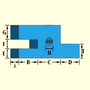
Ainner = πHA
ATotal = Aouter + Ainner
Volume, V, consists of the block, minus the one hole,
V = A [ B(G + E) + C(E + F+ G) +DI ] - πAH2/4
| Value | Equations | WE Program |
| Case 1 | ||
| Surface Area | 344.6 in2 | 344.6 in2 |
| Volume | 236.6 in3 | |
| Part Weight | 8.547 lb | 8.547 lb |
| Case 2 | ||
| Surface Area | 241.9 cm2 | 241.9 cm2 |
| Volume | 159.6 cm3 | |
| Part Weight | 0.3519 lb | 0.3519 lb |
Conversion Constants to
determine part weight in lb
1 gm/cm3 = 2.2046×10⁻⁶ lb/mm3
= 0.036127 lb/in3
| Case Number | ||
| Parameter | 1 | 2 |
| A | 3 in | 3 cm |
| B | 5 in | 3 cm |
| C | 6 in | 3 cm |
| D | 5 in | 3 cm |
| E | 2 in | 3 cm |
| F | 2 in | 3 cm |
| G | 3 in | 3 cm |
| H | 2 in | 1 cm |
| I | 3 in | 3 cm |
| test density |
1 gm/cm3 | 1 gm/cm3 |
17 Dec 2020 - Kurt Gramoll
1) Surface equations incorrectly included inner surface with outer surface. New equation separated outer and inner surfaces.
Similar to the Anchor Pin, the Plate No. 1 Pin object has two tapered cylinders at each end. The tapered cylinders are assumed to go inward, thus A and should be smaller than D. The middle section is a cylindrical shape with a diameter of D.
All sections are considered to be solid.
Technical Calculations
The equation for a tapered cylinder section is derived in the "Solid Ogive" (not a real ogive shape). The derivation will not be duplicated here. The the tapered cylinder volumes are
VTapered Cyl = π B (A2 + D2 + AD) /12
The outside surface area is just the average perimeter times the slope length (see "Solid Ogive" for derivation). This equation is only for the side and does not include the circular area at the top or bottom.
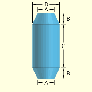
STapered Side = [π(D + A)/2] [(D - A)2/4 + B2]0.5
Outer Surface Area, Aouter, consists of two tapered cylinders, top and and bottom circular area, and on solid cylinder side,
Aouter = π(D + A) [(D - A)2/4 + B2]0.5
+ πDC + πA2/2
Inner Surface Area, Ainner, no inside surface,
Ainner = 0
ATotal = Aouter + Ainner
Volume, V, consists of two solid tapered cylinders and on solid cylinder
V = π B (A2 + D2 + AD) /6 + πD2C /4
| Value | Equations | WE Program |
| Case 1 | ||
| Surface Area | 196.0 in2 | 196.0 in2 |
| Volume | 208.4 in3 | |
| Part Weight | 7.529 lb | 7.529 lb |
| Case 2 | ||
| Surface Area | 846.1 cm2 | 846.1 cm2 |
| Volume | 2,145 cm3 | |
| Part Weight | 4.728 lb | 4.728 lb |
| Case Number | ||
| Parameter | 1 | 2 |
| A | 3 in | 12 cm |
| B | 2 in | 3 cm |
| C | 8 in | 8 cm |
| D | 5 in | 3 cm |
| test density |
1 gm/cm3 | 1 gm/cm3 |
Conversion Constants to
determine part weight in lb
1 gm/cm3 = 2.2046×10⁻⁶ lb/mm3
= 0.036127 lb/in3
While this object is called a Plate, it is assumed to be circular. For rectangular shaped plate, the Rectangular Solid shape should be used.
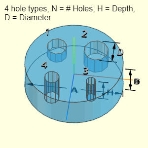
The plate can have up to four different hole types. Not all four types must be used (just leave those input fields blank). Each hole type can have a different number of holes (N), depth (H), and diameter (D). Each hole type is labeled with its number after N, H and D, such as N2, H2 and D2.
The location of the holes is not needed for volume and surface area calculations. But it is assumed that the holes diameters are not large, and they will be contained inside the plate diameter, A. Also, it is assumed that a given hole depth does not exceed the plate thickness, C.
Technical Calculations
Outer Surface Area, Aouter, consists of the cylinder and subtraction of the holes (four possible types). Note, if any of the hole lengths, H, are equal to the block thickness, C, then there is no hole end. The other hole end needs to be subtracted from Aoutter using an if statement in code.
Aouter = Ablock - Ahole ends
= πA2/4 + πAB
- (πD12/4) N1 - (πD22/4) N2
- (πD32/4) N3 - (πD42/4) N4
Inner Surface Area, Ainner, consists of the hole cylindrical surface and one end. Note, if any of the hole lengths, H, are equal to the block thickness, C, then there is no hole end. The hole end needs to be subtracted from Ainner using an if statement in code.
Ainner = Ahole cylinders + Ahole ends
= (πD1) H1 N1 + (πD2) H2 N2
+ (πD3) H3 N3 + (πD4) H4 N4
+ (πD12/4) N1 + (πD22/4) N2
+ (πD32/4) N3 + (πD42/4) N4
ATotal = Aouter + Ainner
Volume, V, consists of the block, minus all four types of holes.
V = πA2B/4 - (πD12/4) H1 N1 - (πD22/4) H2 N2
- (πD32/4) H3 N3 - (πD42/4) H4 N4
| CAUTION |
Calculations do NOT check if
|
| Value | Equations | WE Program |
| Case 1 | ||
| Surface Area | 21.32 in2 | 21.32 in2 |
| Volume | 54.33 in3 | |
| Part Weight | 1.963 lb | 1.963 lb |
| Case 2 | ||
| Surface Area | 375.4 cm2 | 375.4 cm2 |
| Volume | 268.2 cm3 | |
| Part Weight | 0.5913 lb | 0.5913 lb |
Conversion Constants to
determine part weight in lb
1 gm/cm3 = 2.2046×10⁻⁶ lb/mm3
= 0.036127 lb/in3
| Case Number | ||
| Parameter | 1 | 2 |
| A | 6 in | 8 cm |
| B | 5 in | 6 cm |
| D1 | 0.75 in | 0.5 cm |
| H1 | 0.5 in | 6 cm |
| N1 | 1 | 4 |
| D2 | 0.125 in | 1 cm |
| H2 | 1 in | 5 cm |
| N2 | 2 | 3 |
| D3 | 0.5 in | 1.5 cm |
| H3 | 1.5 in | 3 cm |
| N3 | 5 | 2 |
| D4 | 0.325 in | 2 cm |
| H4 | 2 in | 2 cm |
| N4 | 3 | 1 |
| test density |
1 gm/cm3 | 1 gm/cm3 |
14 Dec 2020 - Kurt Gramoll
1) Equations were modified in the program to match the above equations. Previously, inside surface of holes only included one hole end even when N > 1.
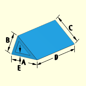
The basic Prism object is a three sided extruded shape. For the "Hollow Prism A and C Open" shape, there is a hollow three sided shape going the length, D, of the prism. Both ends are open. The thickness, A, is constant and equal on all sides.
Technical Calculations
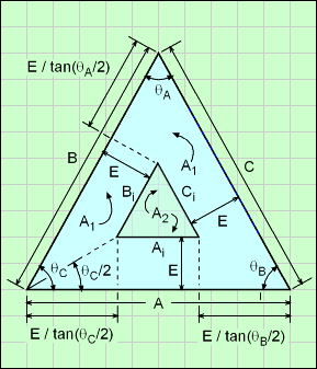
Before actual surfaces and volumes are calculated, various dimensions and angles are required. The diagram shows new constants that are needed.
Using the Law of Cosines,
θA = cos-1[ (B2 + C2 - A2) / (2 B C) ]
θB = cos-1[ (A2 + C2 - B2) / (2 A C) ]
θC = cos-1[ (A2 + B2 - C2) / (2 A B) ]
Inside triangle edge dimensions,
Ai = A - E [ 1/tan(θC/2)+ 1/tan(θB/2) ]
Bi = B - E [ 1/tan(θC/2)+ 1/tan(θA/2) ]
Ci = C - E [ 1/tan(θB/2)+ 1/tan(θA/2) ]
To find the area A1 (triangle area of ABC) and A2 (triangle area of cut out AiBiCi), use Heron's Formula,
A1 = [ P1 (P1 - A) (P1 - B) (P1 - C) ]0.5
where P1 = (A + B + C) / 2
A2 = [ P2 (P2 - Ai) (P2 - Bi) (P2 - Ci) ]0.5
where P2 = (Ai + Bi + Ci) / 2
Using the new inside triangle dimensions with the calculated areas A1 and A2, the volume, inside surface area and outside surface area are,
V = (A1 - A2) D
Aouter = (A + B + C) D + 2 (A1 - A2)
Ainner = (Ai + Bi + Ci) D
| CAUTION |
1. Calculations do NOT check if sides A, B, and C make a real triangle. For example, if B + C < A then a triangle is not possible. 2. Calculations do not check if E is larger than the half the height of the prism in any direction. |
| Value | Equations | WE Program |
| Case 1 | ||
| Surface Area | 233.6 in2 | 233.6 in2 |
| Volume | 103.8 in3 | |
| Part Weight | 3.750 lb | 3.750 lb |
| Case 2 | ||
| Surface Area | 747.7 cm2 | 747.7 cm2 |
| Volume | 623.1 cm3 | |
| Part Weight | 1.374 lb | 1.374 lb |
| Case Number | ||
| Parameter | 1 | 2 |
| A | 8 in | 12 cm |
| B | 5 in | 14 cm |
| C | 6 in | 16 cm |
| D | 8 in | 10 cm |
| E | 1 in | 2 cm |
| test density |
1 gm/cm3 | 1 gm/cm3 |
Conversion Constants to
determine part weight in lb
1 gm/cm3 = 2.2046×10⁻⁶ lb/mm3
= 0.036127 lb/in3
27 Nov 2020 - Kurt Gramoll
1) Equations were modified in the program to match the above equations. Previously, the calculations used arcsin which gave incorrect angle when any angle was over 90o. The correct method uses the arccos formulation for the triangle angles. Derivation details are given above.
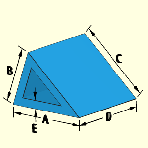
The basic Prism object is a three sided extruded shape. For the "Hollow Prism A or C Open" shape, there is a hollow three sided shape going the length, D, of the prism with one end capped. Only one end is open. The thickness, A, is constant and equal on all sides, including the capped end.
Technical Calculations
Before actual surfaces and volumes are calculated, various dimensions and angles are required. The diagram shows new constants that are needed.
Using the Law of Cosines,
θA = cos-1[ (B2 + C2 - A2) / (2 B C) ]
θB = cos-1[ (A2 + C2 - B2) / (2 A C) ]
θC = cos-1[ (A2 + B2 - C2) / (2 A B) ]
Inside triangle edge dimensions,
Ai = A - E [ 1/tan(θC/2)+ 1/tan(θB/2) ]
Bi = B - E [ 1/tan(θC/2)+ 1/tan(θA/2) ]
Ci = C - E [ 1/tan(θB/2)+ 1/tan(θA/2) ]
To find the area A1 (triangle area of ABC) and A2 (triangle area of cut out AiBiCi), use Heron's Formula,
A1 = [ P1 (P1 - A) (P1 - B) (P1 - C) ]0.5
where P1 = (A + B + C) / 2
A2 = [ P2 (P2 - Ai) (P2 - Bi) (P2 - Ci) ]0.5
where P2 = (Ai + Bi + Ci) / 2
Using the new inside triangle dimensions with the calculated areas A1 and A2, the volume, inside surface area and outside surface area are,
V = (A1 - A2) D + E A2
Aouter = (A + B + C) D + (2A1 - A2)
Ainner = (Ai + Bi + Ci) (D - E) + A2

| CAUTION |
1. Calculations do NOT check if sides A, B, and C make a real triangle. For example, if B + C < A then a triangle is not possible. 2. Calculations do not check if E is larger than the half the height of the prism in any direction. |
| Value | Equations | WE Program |
| Case 1 | ||
| Surface Area | 230.6 in2 | 230.6 in2 |
| Volume | 105.8 in3 | |
| Part Weight | 3.823 lb | 3.823 lb |
| Case 2 | ||
| Surface Area | 745.2 cm2 | 745.2 cm2 |
| Volume | 661.2 cm3 | |
| Part Weight | 1.458 lb | 1.458 lb |
| Case Number | ||
| Parameter | 1 | 2 |
| A | 8 in | 12 cm |
| B | 5 in | 14 cm |
| C | 6 in | 16 cm |
| D | 8 in | 10 cm |
| E | 1 in | 2 cm |
| test density |
1 gm/cm3 | 1 gm/cm3 |
Conversion Constants to
determine part weight in lb
1 gm/cm3 = 2.2046×10⁻⁶ lb/mm3
= 0.036127 lb/in3
28 Nov 2020 - Kurt Gramoll
1) Equations were modified in the program to match the above equations. Previously, the calculations used arcsin which gave incorrect angle when any angle was over 90o. The correct method uses the arccos formulation for the triangle angles. Derivation details are given above.
The basic Prism object is a three sided extruded shape. For the "Hollow Prism B Open" shape, there is a hollow cut out on one side (labeled B). The cutout shape is also a basic three sided prism scaled the same as the full prism. Thus, the wall thickness is the same for all sides, including the two ends.
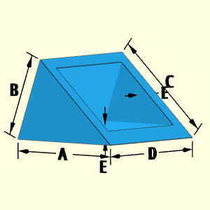
Technical Calculations
Before actual surfaces and volumes are calculated, various dimensions and angles are required. The diagram shows new constants that are needed.
Using the Law of Cosines,
θA = cos-1[ (B2 + C2 - A2) / (2 B C) ]
θB = cos-1[ (A2 + C2 - B2) / (2 A C) ]
θC = cos-1[ (A2 + B2 - C2) / (2 A B) ]
Using trigonometry,
CA = E / sinθB
CB = E / sinθA
Inside triangle edge dimensions,
Ai = A - E [ 1/tanθB + 1/tan(θC/2) ]
Bi = B - E [ 1/tanθA + 1/tan(θC/2) ]
Ci = C - CA - CB
= C - E [1/sinθB + 1/sinθA]
To find the area A1 (triangle area of ABC) and A2 (triangle area of cut out AiBiCi), use Heron's Formula,
A1 = [ P1 (P1 - A) (P1 - B) (P1 - C) ]0.5
where P1 = (A + B + C) / 2
A2 = [ P2 (P2 - Ai) (P2 - Bi) (P2 - Ci) ]0.5
where P2 = (Ai + Bi + Ci) / 2
Finally, volume, inside surface area and outside surface area are,
V = (A1 - A2) D
Aouter = (B + A) D + (CA + CB) D + 2 (A1 - A2)
Ainner = (Bi + Ai) D
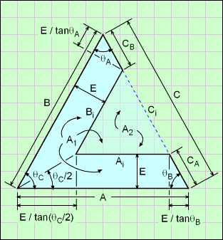
| CAUTION |
1. Calculations do NOT check if sides A, B, and C make a real triangle. For example, if B + C < A then a triangle is not possible. 2. Calculations do not check if E is larger than the height of the prism in any direction. |
| Value | Equations | WE Program |
| Case 1 | ||
| Surface Area | 215.3 in2 | 215.3 in2 |
| Volume | 91.04 in3 | |
| Part Weight | 3.289 lb | 3.289 lb |
| Case 2 | ||
| Surface Area | 698.8 cm2 | 698.8 cm2 |
| Volume | 587.5 cm3 | |
| Part Weight | 1.295 lb | 1.295 lb |
| Case Number | ||
| Parameter | 1 | 2 |
| A | 8 in | 12 cm |
| B | 5 in | 14 cm |
| C | 6 in | 16 cm |
| D | 8 in | 10 cm |
| E | 1 in | 2 cm |
| test density |
1 gm/cm3 | 1 gm/cm3 |
Conversion Constants to
determine part weight in lb
1 gm/cm3 = 2.2046×10⁻⁶ lb/mm3
= 0.036127 lb/in3
27 Nov 2020 - Kurt Gramoll
1) Equations were modified in the program to match the above equations. Previously, the calculations used arcsin which gave incorrect angle when any angle was over 90o. The correct method uses the arccos formulation for the triangle angles. Derivation details are given above.
2) Old equations had division by zero, incorrect alpha angle. Corrected but old equations not used (see previous item number 1).
The basic Prism object is a three sided extruded shape. For the "Hollow Prism B Open V Shape " shape, there is a cutout along the length of the prism (D). The cutout shape is also a simple three sided prism scaled the same as the full prism. One side of the cutout touches side C so the final shape looks like a 'V". The wall thickness is the same for all sides, including the two ends.
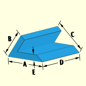
Technical Calculations
Before actual surfaces and volumes are calculated, various dimensions and angles are required. The diagram shows new constants that are needed.
Using the Law of Cosines,
θA = cos-1[ (B2 + C2 - A2) / (2 B C) ]
θB = cos-1[ (A2 + C2 - B2) / (2 A C) ]
θC = cos-1[ (A2 + B2 - C2) / (2 A B) ]
Using trigonometry,
CA = E / sinθB
CB = E / sinθA
Inside triangle edge dimensions,
Ai = A - E [ 1/tanθB + 1/tan(θC/2) ]
Bi = B - E [ 1/tanθA + 1/tan(θC/2) ]
Ci = C - CA - CB
= C - E [1/sinθB + 1/sinθA]
To find the area A1 (triangle area of ABC) and A2 (triangle area of cut out AiBiCi), use Heron's Formula,
A1 = [ P1 (P1 - A) (P1 - B) (P1 - C) ]0.5
where P1 = (A + B + C) / 2
A2 = [ P2 (P2 - Ai) (P2 - Bi) (P2 - Ci) ]0.5
where P2 = (Ai + Bi + Ci) / 2
Finally, volume, inside surface area and outside surface area are,
V = (A1 - A2) D
Aouter = (B + A) D + (CA + CB) D + 2 (A1 - A2)
Ainner = (Bi + Ai) D

| CAUTION |
1. Calculations do NOT check if sides A, B, and C make a real triangle. For example, if B + C < A then a triangle is not possible. 2. Calculations do not check if E is larger than the height of the prism in any direction. |
| Value | Equations | WE Program |
| Case 1 | ||
| Surface Area | 204.1 in2 | 204.1 in2 |
| Volume | 81.44 in3 | |
| Part Weight | 2.942 lb | 2.942 lb |
| Case 2 | ||
| Surface Area | 575.4 cm2 | 575.4 cm2 |
| Volume | 436.9 cm3 | |
| Part Weight | 0.9631 lb | 0.9632 lb |
| Case Number | ||
| Parameter | 1 | 2 |
| A | 8 in | 12 cm |
| B | 5 in | 14 cm |
| C | 6 in | 16 cm |
| D | 8 in | 10 cm |
| E | 1 in | 2 cm |
| test density |
1 gm/cm3 | 1 gm/cm3 |
Conversion Constants to
determine part weight in lb
1 gm/cm3 = 2.2046×10⁻⁶ lb/mm3
= 0.036127 lb/in3
28 Nov 2020 - Kurt Gramoll
1) Equations were modified in the program to match the above equations. Previously, the calculations used arcsin which gave incorrect angle when any angle was over 90o. The correct method uses the arccos formulation for the triangle angles. Derivation details are given above.
The basic Prism object is a simple three sided extruded shape. For the "Solid Prism" shape, there center is solid.
Technical Calculations
The area of a triangle, Atri, can be calculated if the length of each side is known. This is called Heron's Formula. Using A, B, and C as the length of each side, the triangle area is
![]()
where p = (A + B + C) / 2
Outer Surface Area, Aouter, is calculated by using the area of each of the two triangular ends, Atri, and adding the three rectangular surfaces between the two ends.
Aouter = 2 Atri + (A + B + C) D
Volume, V, of the solid prism is the area of the triangular end, Atri, times its length.
V = D Atri

| CAUTION |
Calculations do NOT check if sides A, B, and C make a real triangle. For example, if B + C < A then a triangle is not possible. |
| Value | Equations | WE Program |
| Case 1 | ||
| Surface Area | 32.81 in2 | 32.81 in2 |
| Volume | 8.714 in3 | |
| Part Weight | 0.3148 lb | 0.3148 lb |
| Case 2 | ||
| Surface Area | 813.3 cm2 | 582.7 cm2 |
| Volume | 813.3 cm3 | |
| Part Weight | 1.793 lb | 1.793 lb |
| Case Number | ||
| Parameter | 1 | 2 |
| A | 4 in | 12 cm |
| B | 2 in | 14 cm |
| C | 3 in | 16 cm |
| D | 3 | 10 |
| test density |
1 gm/cm3 | 1 gm/cm3 |
Conversion Constants to
determine part weight in lb
1 gm/cm3 = 2.2046×10⁻⁶ lb/mm3
= 0.036127 lb/in3
The Projectile Body shape is only one of two shapes that are over defined, caused an over constraint system (the other is the Upper Body). It can be noted, that I, J with E and F can be used to determine the location of the radius arc for both the top and bottom curves. But, this arc curve center and length can also be determined by the two points on the curve and a tangent line at one of the points. Thus, it is over constraint.
This shape has 5 redundant dimensions, I, J, C, D and G. G is defined with E and F. The inside dimensions C and D are defined by the outside dimensions and the thickness set at L (vertical distance).
If I, J, C, D and G are not used, then the shape can be determined. The actual weight equations do use I, J, C, D and G, so it has not been deleted from the Weight Estimator input page.

This over constraint condition can be seen by noticing the inside arc, top or bottom half, can be defined by two points on the curve and one tangent line. The circle diagram shows that two points and a tangent line through one of the points can define a curve without needing the radius I or J, or the location of the center point. The two points on the shape are defined by A and F (also the tangent line), and by B and F for the lower portion. The upper portion is similar.
| CAUTION |
Should not be used - Shape is not physically possible with the given inputs. Needs to be removed or input variables reduced. |
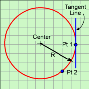
4 Jan 2021 - Kurt Gramoll
1) Equations not correct. Cannot update since the shape is not physically possible. Input variables need to be reduced.
The Hollow Projectile A Closed shape has an ogive (a partial circular arc curve) top section and a cylindrical bottom section. Both sections are hollow. The rate of curvature of the top section can be changed by modifying the radius dimension, D. The location of arc cure ('+' symbol) is determined by the program to match the other dimensions and D.
It is possible to have a non-tangent connection between the top and bottom sections at their common joint.
The thickness is defined by the difference of A and E (and divided by 2), and is constant in both sections.
The bottom is enclosed. The thickness of the bottom is assumed to be the same as the upper shell wall.
The horizontal line between the ogive section and cylinder, the top vertical line at the joint, and vertical line at the bottom center do not technically exist. They are artifacts from the 3D modeling program.
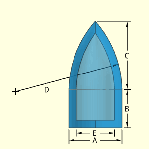
The location of the arc center, the '+' symbol on diagram, is determined from the lower point of C dimension (adjacent to B dimension) and the tip. Both these points are known.
As illustrated in the circle diagram, two points and the radius can define an arc curve without needing other dimensions. There is a second possible circular arc (dashed line), but it is not realistic so is not considered for the shape.

Technical Calculations
There are two sub-shapes that make up the Hollow Projectile with a closed end, an ogive solid of revolution and cylinder. Cylinder surface and volume is well known, but the ogive solid surface and solid equations need to be derived and explained. This section will concentrate on the ogive solid (curved top section).
First, the ogive curve needs to be established. Then it can be revolved to create the solid. Recall, an ogive curve is a section of a circular arc as mentioned in introduction section above. The ogive needs to be described as an equation in an x-y cartesian coordinate system so it can be integrated about the x-axis to generate a solid.
The diagram at the right shows the Ogive Curve (red line) that describes the edge of the upper section of the projectile. That curve is rotated about the x-axis giving the upper solid projectile shape. The lower shape is the cylindrical section.
The final curve equation is (see Solid Projectile for derivation details),y = [D2 - (x - D cosα)2]0.5 - D sinα
This form is important so that the curve can be rotated about the x-axis to give a solid. The parameters A, B, C and D are the input variables in the Weight Estimator program.
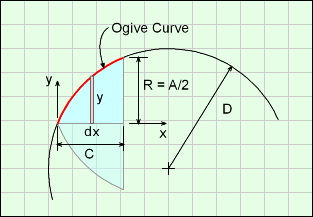
Using the ogive curve, the volume can be calculated as (see Solid Projectile for details),
V = π [ (D2 + b12 - a12) C + a1 C2 - C3/3]
- π b1 { (C-a1) [D2 - (C-a1)2]0.5 + D2 sin-1[ (C-a1)/D] }
+ π b1 { (-a1) [D2 - a12]0.5 + D2 sin-1[ (-a1)/D] }
where a1 = D cosα and b1 = D sinα
The surface is,
S = 2πD [ C + b1 sin-1[(a1 - C)/D] + b1 sin-1(C/D) ]
The V and S equations work for both solid and hollow sections of the shape.
The vertical wall thickness at the point, tp, is not the same as the wall thickness at the tangent point, tt. nor the perpendicular thickness, t,at any point on the curve. This can be seen in the diagram at the right. Therefore, new dimensions Din, Cin are needed to calculate the inside hollow volume and surface using the above equations. If the known tt is used to find Din and Cin, there error will be 3-4% for thick walled projectiles.
The inside radius is E/2 where E is a known input variable. The new inside radius of curvature, Din, can be found using the angle α and Pythagoras' theorem (triangle 1),
Din = [ (D sinα + E/2)2 + (D cosα - C)2 ]0.5
Note, E, D, and C are the input variables and are not calculated variables. The angle α is calculated from the equation derived in the solid projectile section.
The distance Cin is also needed. It can also be found angle α and pythagoras' theorem (triangle 2) along with the new dimension, Din,
Din2 = [ (D sinα)2 + (D cosα - C + Cin)2 ]0.5
Cin = [ Din2+ (D sinα)2]0.5 - (D cosα - C)
The new variables, Din and Cin are used for interior hollow volume and inner surface.
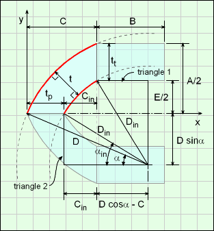
| Value | Equations | WE Program |
| Case 1 | ||
| Surface Area | 453.6 in2 | 453.6 in2 |
| Volume | 334.0 in3 | |
| Part Weight | 8.094 lb | 8.094 lb |
| Case 2 | ||
| Surface Area | 616.2 cm2 | 616.2 cm2 |
| Volume | 304.7 cm3 | |
| Part Weight | 0.6717 lb | 0.6717 lb |
| Case Number | ||
| Parameter | 1 | 2 |
| A | 7 in | 8 cm |
| B | 5 in | 4 cm |
| C | 9 in | 12 cm |
| D | 14 in | 16 cm |
| E | 5 in | 6 cm |
| test density |
1 gm/cm3 | 1 gm/cm3 |
Conversion Constants to
determine part weight in lb
1 gm/cm3 = 2.2046×10⁻⁶ lb/mm3
= 0.036127 lb/in3
5 Dec 2020
1) The equations in WE were changed to the equations derived above. The old equations did not adjust D for smaller inside hollow shape and they incorrectly used wall thickness at tangent for vertical wall thickness at the point (top). The wall thickness perpendicular to the surface is constant. Also, the 'offset' variable (calculated in subroutine) did not adjust A, C or D for the smaller shape. Error was 3-4% for thick projectile shapes.
2) LEFT OUT weight of the bottom disk, missing volume = π A2 (A-E)/4. Fixed so this volume is included.
The Hollow Projectile A Open shape has an ogive (a partial circular arc curve) top section and a cylindrical bottom section. Both sections are hollow. The rate of curvature of the top section can be changed by modifying the radius dimension, D. The location of arc cure ('+' symbol) is determined by the program to match the other dimensions and D.
It is possible to have a non-tangent connection between the top and bottom sections at their common joint.
The thickness is defined by the difference of A and E (and divided by 2), and is constant in both sections.
The horizontal line between the ogive section and cylinder, and the top vertical line at the joint do not technically exist. They are artifacts from the 3D modeling program.
The dimension D is for the arc length from the arc circular center ('+' location) to the outside surface. Dimension D does not represent an angle.
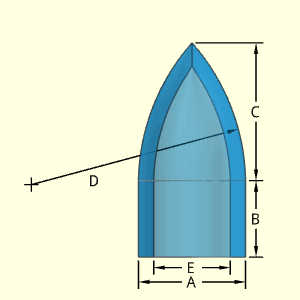
The location of the arc center, the '+' symbol on diagram, is determined from the lower point of C dimension (adjacent to B dimension) and the tip. Both these points are known.
As illustrated in the circle diagram, two points and the radius can define an arc curve without needing other dimensions. There is a second possible circular arc (dashed line), but it is not realistic so is not considered for the shape.

Technical Calculations
There are two sub-shapes that make up the Hollow Projectile with an open end, an ogive solid of revolution and cylinder. Cylinder surface and volume is well known, but the ogive solid surface and solid equations need to be derived and explained. This section will concentrate on the ogive solid (curved top section).
First, the ogive curve needs to be established. Then it can be revolved to create the solid. Recall, an ogive curve is a section of a circular arc as mentioned in introduction section above. The ogive needs to be described as an equation in an x-y cartesian coordinate system so it can be integrated about the x-axis to generate a solid.
The diagram at the right shows the Ogive Curve (red line) that described the edge of the upper section of the projectile. That curve is rotated about the x-axis giving the upper solid projectile shape. The lower shape is the cylindrical section.
The final curve equation is (see Solid Projectile for derivation details),y = [D2 - (x - D cosα)2]0.5 - D sinα
This form is important so that the curve can be rotated about the x-axis to give a solid. The parameters A, B, C and D are the input variables in the Weight Estimator program.

Using the ogive curve, the volume can be calculated as (see Solid Projectile for details),
V = π [ (D2 + b12 - a12) C + a1 C2 - C3/3]
- π b1 { (C-a1) [D2 - (C-a1)2]0.5 + D2 sin-1[ (C-a1)/D] }
+ π b1 { (-a1) [D2 - a12]0.5 + D2 sin-1[ (-a1)/D] }
where a1 = D cosα and b1 = D sinα
The surface is,
S = 2πD [ C + b1 sin-1[(a1 - C)/D] + b1 sin-1(C/D) ]
The V and S equations work for both solid and hollow sections of the shape.
The vertical wall thickness at the point, tp, is not the same as the wall thickness at the tangent point, tt. nor the perpendicular thickness, t, at any point on the curve. This can be seen in the diagram at the right. Therefore, new dimensions Din, Cin are needed to calculate the inside hollow volume and surface using the above equations. If the known tt is used to find Din and Cin, there error will be 3-4% for thick walled projectiles.
The inside radius is E/2 where E is a known input variable. The new inside radius of curvature, Din, can be found using the angle α and pythagoras' theorem (triangle 1),
Din = [ (D sinα + E/2)2 + (D cosα - C)2 ]0.5
Note, E, D, and C are the input variables and are not calculated variables. The angle α is calculated from the equation derived in the solid projectile section.
The distance Cin is also needed. It can also be found angle α and pythagoras' theorem (triangle 2) along with the new dimension, Din,
Din2 = [ (D sinα)2 + (D cosα - C + Cin)2 ]0.5
Cin = [ Din2+ (D sinα)2]0.5 - (D cosα - C)
The new variables, Din and Cin are used for interior hollow volume and inner surface.

| Value | Equations | WE Program |
| Case 1 | ||
| Surface Area | 430.0 in2 | 430.0 in2 |
| Volume | 204.4 in3 | |
| Part Weight | 7.384 lb | 7.384 lb |
| Case 2 | ||
| Surface Area | 578.5 cm2 | 578.5 cm2 |
| Volume | 276.4 cm3 | |
| Part Weight | 0.6094 lb | 0.6094 lb |
| Case Number | ||
| Parameter | 1 | 2 |
| A | 7 in | 8 cm |
| B | 5 in | 4 cm |
| C | 9 in | 12 cm |
| D | 14 in | 16 cm |
| E | 5 in | 6 cm |
| test density |
1 gm/cm3 | 1 gm/cm3 |
Conversion Constants to
determine part weight in lb
1 gm/cm3 = 2.2046×10⁻⁶ lb/mm3
= 0.036127 lb/in3
5 Dec 2020
1) The equations in WE were changed to the equations derived above. The old equations did not adjust D for smaller inside hollow shape and they incorrectly used wall thickness at tangent for vertical wall thickness at the point (top). The wall thickness perpendicular to the surface is constant. Also, the 'offset' variable (calculated in subroutine) did not adjust A, C or D for the smaller shape. Error was 3-4% for thick projectile shapes.
The Solid Projectile A Open shape has an ogive (a partial circular arc curve) top section and a cylindrical bottom section. Both sections are solid. The rate of curvature of the top section can be changed by modifying the radius dimension, D. The location of arc cure ('+' symbol) is determined by the program to match the other dimensions and D.
It is possible to have a non-tangent connection between the top and bottom sections at their common joint.
The horizontal line between the ogive section and cylinder section does not technically exist. It is an artifact from the 3D modeling program.
The dimension D is for the arc length from the arc circular center ('+' location) to the outside surface. Dimension D does not represent an angle.
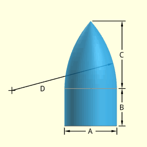
The location of the arc center, the '+' symbol on diagram, is determined from the lower point of C dimension (adjacent to B dimension) and the tip. Both these points are know.
As illustrated in the circle diagram, two points and the radius can define an arc curve without needing other dimensions. There is a second possible circular arc (dashed line), but it is not realistic so is not considered for the shape.

Technical Calculations
There are two sub-shapes that make up the solid projectile, an ogive solid of revolution and cylinder. Cylinder surface and volume is well known, but the ogive solid surface and solid equations need to be derived and explained. This section will concentrate on the ogive solid (curved top section).
First, the ogive curve needs to be established. Then it can be revolved to create the solid. Recall, an ogive curve is a section of a circular arc as mentioned in introduction section above. The ogive needs to be described as an equation in an x-y cartesian coordinate system so it can be used to generate a solid.
The diagram at the right shows the Ogive Curve (red line) that described the edge of the upper section of the projectile. That curve is rotated about the x-axis giving the upper solid projectile shape. The lower shape is the cylindrical section.
First, the angle α is
α = γ - θ
Angles γ and θ can be determined using the right triangle that is inscribed in the circle of radius D.
α = cos-1[ (R2 + C2)0.5 / (2D) ] - tan-1(R/C)
The Ogive Curve can then be modeled as a section of a circle the x'-y' coordinate system,
x'2 + y'2 = D2
Next, t he x'-y' coordinate system can be translated into the x-y coordinate system as,
(x - D cosα)2 + (y + D sinα)2 = D2
Rearranging gives,
y = [D2 - (x - D cosα)2]0.5 - D sinα
This form is important so that the curve can be rotated about the x-axis to give a solid. The parameters A, B, C and D are the input variables in the Weight Estimator program.
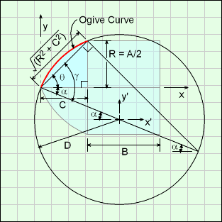
Using the Ogive curve, the volume can be calculated by considering a series of disks, and integrating them the length of projectile, C,

For simplification, let a1 = D cosα and b1 = D sinα. Completing the integration using math tables (steps not shown) gives,
V = π [ (D2 + b12 - a12) C + a1 C2 - C3/3]
- π b1 { (C-a1) [D2 - (C-a1)2]0.5 + D2 sin-1[ (C-a1)/D] }
+ π b1 { (-a1) [D2 - a12]0.5 + D2 sin-1[ (-a1)/D] }

Similarly, the surface can be determined by integrating the circumference of the element dx. The slope distance is included (square root term), giving
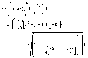
where a1 = D cosα and b1 = D sinα. While this looks messy, using basic algebra, it actually simplifies to

Completing the integration using math tables (steps not shown) gives,
S = 2πD [ C + b1 sin-1[(a1 - C)/D] + b1 sin-1(C/D) ]
| Value | Equations | WE Program | Wolfram Alpha* |
| Case 1 | |||
| Surface Area | 289.8 in2 | 289.8 in2 | 289.8 in2 |
| Volume | 380.3 in3 | 380.3 in3 | |
| Part Weight | 13.74 lb | 13.74 lb | |
| Case 2 | |||
| Surface Area | 381.4 cm2 | 381.4 cm2 | 381.4 cm2 |
| Volume | 575.9 cm3 | 575.9 cm3 | |
| Part Weight | 1.270 lb | 1.270 lb |
*Calculations done at www.WolframAlpha.com
Input used "volume of revolved solid"
and "surface of revolved solid"
| Case Number | ||
| Parameter | 1 | 2 |
| A | 7 in | 8 cm |
| B | 5 in | 4 cm |
| C | 9 in | 12 cm |
| D | 14 in | 16 cm |
| test density |
1 gm/cm3 | 1 gm/cm3 |
Conversion Constants to
determine part weight in lb
1 gm/cm3 = 2.2046×10⁻⁶ lb/mm3
= 0.036127 lb/in3
2 Dec 2020
1) The equations in WE were changed to the equations derived above. The old equations did give the correct volume and surface, but they were not documented.
The Pyramid Tetrahedron shape is special four side polygon with all sides identical size. This means all edges have the same length, A. Note, the height of this shape is not A, just the individual sides.
Be careful not to confuse this shape with a true pyramid which has five sides (see Pyramid shape).
Technical Calculations
Outer Surface Area, Aouter,
Aouter = 30.5 A2
Inner Surface Area, Ainner, does not exist.
Ainner = 0
ATotal = Aouter + Ainner
Volume, V, consists of a single sphere.
V = A3 12 / 20.5
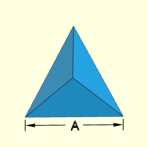
| Value | Equations | WE Program |
| Case 1 | ||
| Surface Area | 43.30 in2 | 43.30 in2 |
| Volume | 14.73 in3 | |
| Part Weight | 0.5322 lb | 0.5322 lb |
| Case 2 | ||
| Surface Area | 838.3 cm2 | 838.3 cm2 |
| Volume | 1,255 cm3 | |
| Part Weight | 2.767 lb | 2.767 lb |
| Case Number | ||
| Parameter | 1 | 2 |
| A | 5 in | 22 cm |
| test density |
1 gm/cm3 | 1 gm/cm3 |
Conversion Constants to
determine part weight in lb
1 gm/cm3 = 2.2046×10⁻⁶ lb/mm3
= 0.036127 lb/in3
The Pyramid is a basic 3D pyramid with a rectangular base and four identical triangular sides. The base is defined with A and B dimensions, and the height by the C dimension. All four triangular sides are assumed to be the same.
Do not confuse this with the simpler tetrahedron that has a total of four triangles and no rectangular base.
Technical Calculations
Outer Surface Area, Aouter,
Aouter = AB + A [(B/2)2 + C2]0.5 + B [(A/2)2 + C2]0.5
Inner Surface Area, Ainner, does not exist.
Ainner = 0
ATotal = Aouter + Ainner
Volume, V, consists of a single sphere.
V = A B C / 3
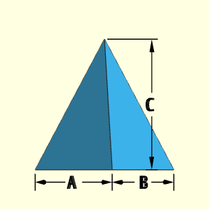
| Value | Equations | WE Program |
| Case 1 | ||
| Surface Area | 77.62 in2 | 77.62 in2 |
| Volume | 40.00 in3 | |
| Part Weight | 1.445 lb | 1.445 lb |
| Case 2 | ||
| Surface Area | 261.7 cm2 | 261.7 cm2 |
| Volume | 720.0 cm3 | |
| Part Weight | 0.5291 lb | 0.5291 lb |
| Case Number | ||
| Parameter | 1 | 2 |
| A | 5 in | 6 cm |
| B | 4 in | 10 cm |
| C | 6 in | 12 cm |
| test density |
1 gm/cm3 | 1 gm/cm3 |
Conversion Constants to
determine part weight in lb
1 gm/cm3 = 2.2046×10⁻⁶ lb/mm3
= 0.036127 lb/in3
The Rear Body shape is a multiple indented cylindrical shape with many dimensions. It is possible to have dimensions any size, such as E larger than A which is not physically possible. Care needs to be take to make sure all dimensions are feasible and realistic.
The vertical center line in the middle does not technically exist. It is simply an artifact from the 3D modeling program.
Technical Calculations
Outer Surface Area, Aouter, includes the top and bottom edge, and the outside cylinders,
Aouter = π(A2 - C2)/4 + π(A2 - F2)/4
+ BπN + Aπ(I - N)
= π (A2/2 - C2/4 - F2/4 + BN + AI - AN)
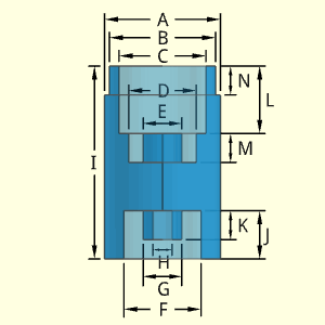
Inner Surface Area, Ainner, is a series of cylinders, including top and bottom interiors surfaces,
Ainner = πC2/4 + CπL + DπM + EπM
+ πF2/4 + FπJ + GπK + HπK
= π (C2 + F2)/4
+ π [CL + M(D+ E) + FJ + K(G + H)]
ATotal = Aouter + Ainner
Volume, V, consists of a series of solid and hollow cylinders. Equation derived by starting with solid cylinder I height and A diameter, and then subtracting hollow cylinders.
V = (π/4) [A2I - (A2 - B2)N - C2L
- (D2 - E2)M - F2J + (G2 - H2)K]
| CAUTION |
Calculations do NOT check if
|
| Value | Equations | WE Program |
| Case 1 | ||
| Surface Area | 1,454 in2 | 1,454 in2 |
| Volume | 1,462 in3 | |
| Part Weight | 52.80 lb | 52.80 lb |
| Case 2 | ||
| Surface Area | 3,720 cm2 | 3,720 cm2 |
| Volume | 6,491 cm3 | |
| Part Weight | 14.31 lb | 14.31 lb |
Conversion Constants to
determine part weight in lb
1 gm/cm3 = 2.2046×10⁻⁶ lb/mm3
= 0.036127 lb/in3
| Case Number | ||
| Parameter | 1 | 2 |
| A | 12 in | 20 cm |
| B | 11 in | 18 cm |
| C | 9 in | 14 cm |
| D | 7 in | 8 cm |
| E | 4 in | 4 cm |
| F | 8 in | 14 cm |
| G | 4 in | 8 cm |
| H | 2 in | 2 cm |
| I | 20 in | 30 cm |
| J | 5 in | 10 cm |
| K | 3 in | 6 cm |
| L | 7 in | 7 cm |
| M | 3 in | 8 cm |
| N | 3 in | 5 cm |
| test density |
1 gm/cm3 | 1 gm/cm3 |
24 Dec 2020 - Kurt Gramoll
The Rectangle Circle is a flat plate object with circular ends. The shape can have up to 4 holes. Minimum holes is 1. The hole(s) depth and diameter can be set, but all holes will be the same. The hole should not be larger than the plate thickness.
Technical Calculations
Outer Surface Area, Aouter, consists of a solid bar with two semi-cylinders on each end. There are possible holes (one type). Note, if any of the hole lengths, F, are equal to the block thickness, C, then there is no hole end. The other hole end needs to be subtracted from Aoutter using an if statement in code.
Aouter = Ablock + Acyl ends - Ahole ends
= 2 (B - A) A + 2 (B - A) C
+ πA2/4 + πAC
- (πD2/4) E
= (B - A)(A + C) + π(A2/2 + AC - D2E/4)

Inner Surface Area, Ainner, consists of the hole cylindrical surface and one end. Note, if any of the hole lengths, F, is equal to the block thickness, C, then there is no hole end. The hole end needs to be subtracted from Ainner using an if statement in code.
Ainner = Ahole cylinders + Ahole ends
= πD FE + (πD2/4) E
ATotal = Aouter + Ainner
Volume, V, consists of the rectangular block with two semi-cylinders at each end, plus one type of hole,
V = (B - A) AC + πA2C /4 - (πD2F /4) E
| CAUTION |
Calculations do NOT check if
|
| Value | Equations | WE Program |
| Case 1 | ||
| Surface Area | 54.85 in2 | 54.85 in2 |
| Volume | 12.00 in3 | |
| Part Weight | 0.4335 lb | 0.4335 lb |
| Case 2 | ||
| Surface Area | 458.2 cm2 | 458.2 cm2 |
| Volume | 440.5 cm3 | |
| Part Weight | 0.9712 lb | 0.9712 lb |
| Case Number | ||
| Parameter | 1 | 2 |
| A | 2 in | 4 cm |
| B | 8 in | 20 cm |
| C | 1 in | 6 cm |
| D | 1 in | 2 cm |
| E | 4 | 3 |
| F | 1 in | 2 cm |
| test density |
1 gm/cm3 | 1 gm/cm3 |
Conversion Constants to
determine part weight in lb
1 gm/cm3 = 2.2046×10⁻⁶ lb/mm3
= 0.036127 lb/in3
23 Dec 2020 - Kurt Gramoll
1) Equations for outside surface did not include circular curved ends. Major oversight. New equations include curved ends
2) Equations did not check if hole was all the way through, and its effect on inside and outside surface area. New equations check if hole is through the bar.
The Rectangle Sold object is a solid plate with four different possible holes. The shape is shown more like a cube due to space restriction on the web page.
The plate can have up to four different hole types. Not all four types must be used (just leave those input fields blank). Each hole type can have a different number of holes (N), depth (H), and diameter (D). Each hole type is labeled with its number after N, H and D, such as N2, H2 and D2.
The location of the holes is not needed for volume and surface area calculations. But it is assumed that the holes diameters are not large, and they will be contained inside the plate dimensions A and B. Also, it is assumed that a given hole depth does not exceed the plate thickness, C.
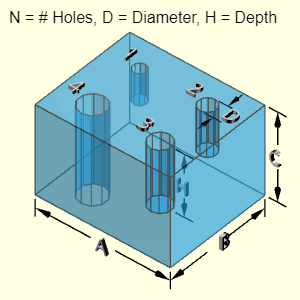
Technical Calculations
Outer Surface Area, Aouter, consists of the outer main block and subtraction of the holes (four possible types). Note, if any of the hole lengths, H, are equal to the block thickness, C, then there is no hole end. The other hole end needs to be subtracted from Aouter using an if statement in code.
Aouter = Ablock - Ahole ends
=2 (A B + B C + C A)
- (πD12/4) N1 - (πD22/4) N2
- (πD32/4) N3 - (πD42/4) N4
Inner Surface Area, Ainner, consists of the hole cylindrical surface and one end. Note, if any of the hole lengths, H, are equal to the block thickness, C, then there is no hole end. The hole end needs to be subtracted from Ainner using an if statement in code.
Ainner = Ahole cylinders + Ahole ends
= (πD1) H1 N1 + (πD2) H2 N2
+ (πD3) H3 N3 + (πD4) H4 N4
+ (πD12/4) N1 + (πD22/4) N2
+ (πD32/4) N3 + (πD42/4) N4
ATotal = Aouter + Ainner
Volume, V, consists of the block, minus all four types of holes.
V = A B C - (πD12/4) H1 N1 - (πD22/4) H2 N2
- (πD32/4) H3 N3 - (πD42/4) H4 N4
| CAUTION |
Calculations do NOT check if
|
| Value | Equations | WE Program |
| Case 1 | ||
| Surface Area | 181.4 in2 | 181.4 in2 |
| Volume | 116.3 in3 | |
| Part Weight | 4.202 lb | 4.202 lb |
| Case 2 | ||
| Surface Area | 416.4 cm2 | 416.4 cm2 |
| Volume | 419.8 cm3 | |
| Part Weight | 0.9254 lb | 0.9254 lb |
Conversion Constants to
determine part weight in lb
1 gm/cm3 = 2.2046×10⁻⁶ lb/mm3
= 0.036127 lb/in3
| Case Number | ||
| Parameter | 1 | 2 |
| A | 6 in | 8 cm |
| B | 5 in | 9 cm |
| C | 4 in | 6 cm |
| D1 | 0.75 in | 0.3 cm |
| H1 | 1.5 in | 2 cm |
| N1 | 1 | 4 |
| D2 | 0.125 in | 0.5 cm |
| H2 | 3 in | 6 cm |
| N2 | 2 | 1 |
| D3 | 0.5 in | 0.7 cm |
| H3 | 2 in | 5 cm |
| N3 | 5 | 3 |
| D4 | 0.325 in | 1.0 cm |
| H4 | 4 in | 3 cm |
| N4 | 3 | 2 |
| test density |
1 gm/cm3 | 1 gm/cm3 |
14 Dec 2020 - Kurt Gramoll
1) Equations were modified in the program to match the above equations. Previously, hole end surfaces where incorrectly added when the hole is all the way through the surface. It ignored both end holes instead of adding two end holes.
The Rectangle Sold object is a hollow rectangular shape with four different possible holes. The holes are assumed to be placed where they penetrate one and only one wall. Each vertical wall (C dimension) has the same thickness, F. The base or floor has a thickness that is the difference between the dimensions C and E. The top is open and has no thickness.
The shape can have up to four different hole types. Not all four types must be used (just leave those input fields blank). Each hole type can have a different number of holes (N), depth (H), and diameter (D). Each hole type is labeled with its number after N, H and D, such as N2, H2 and D2.
The exact location of the holes is not needed for volume and surface area calculations. But it is assumed that the holes diameters are not large, and they will be contained inside the wall section of any vertical wall. Also, it is assumed that a given hole depth does not exceed the wall thickness, F.
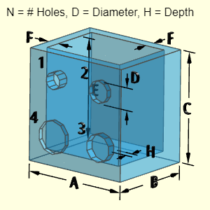
Outer Surface Area, Aouter, consists of the outer main block and subtraction of the holes (four possible types). Note, if any of the hole lengths, H, are equal to the block thickness, C, then there is no hole end.
Aouter = Ablock - Ahole ends
=2 (A B + B C + C A)
- (πD12/4) N1 - (πD22/4) N2
- (πD32/4) N3 - (πD42/4) N4
Inner Surface Area, Ainner, consists of the hole cylindrical surface and one end. Note, if any of the hole lengths, H, are equal to the block thickness, C, then there is no hole end. The hole end needs to be subtracted from Ainner using an if statement in code.
Ainner = Ahole cylinders + Ahole ends
= (πD1) H1 N1 + (πD2) H2 N2
+ (πD3) H3 N3 + (πD4) H4 N4
+ (πD12/4) N1 + (πD22/4) N2
+ (πD32/4) N3 + (πD42/4) N4
ATotal = Aouter + Ainner
Volume, V, consists of the block, minus all four types of holes.
V = A B C - (A - 2F)(B - 2F) E
- (πD12/4) H1 N1 - (πD22/4) H2 N2
- (πD32/4) H3 N3 - (πD42/4) H4 N4
| CAUTION |
Calculations do NOT check if
|
| Value | Equations | WE Program |
| Case 1 | ||
| Surface Area | 778.9 in2 | 778.9 in2 |
| Volume | 367.4 in3 | |
| Part Weight | 13.27 lb | 13.27 lb |
| Case 2 | ||
| Surface Area | 461.7 cm2 | 461.7 cm2 |
| Volume | 327.1 cm3 | |
| Part Weight | 0.7212 lb | 0.7212 lb |
Conversion Constants to
determine part weight in lb
1 gm/cm3 = 2.2046×10⁻⁶ lb/mm3
= 0.036127 lb/in3
| Case Number | ||
| Parameter | 1 | 2 |
| A | 10 in | 8 cm |
| B | 8 in | 9 cm |
| C | 10 in | 6 cm |
| E | 9 in | 5 cm |
| F | 1 in | 2 cm |
| D1 | 0.75 in | 0.3 cm |
| H1 | 0.5 in | 1 cm |
| N1 | 1 | 4 |
| D2 | 0.125 in | 0.5 cm |
| H2 | 0.75 in | 1.5 cm |
| N2 | 2 | 1 |
| D3 | 0.25 in | 0.7 cm |
| H3 | 0.6 in | 1 cm |
| N3 | 5 | 3 |
| D4 | 0.325 in | 1.0 cm |
| H4 | 1 in | 2 cm |
| N4 | 3 | 2 |
| test density |
1 gm/cm3 | 1 gm/cm3 |
15 Dec 2020 - Kurt Gramoll
1) Equations were modified in the program to match the above equations. Previously, hole end surfaces where incorrectly added when the hole is all the way through the surface. It ignored both end holes instead of adding two end holes.
The Sheath Hollow C Closed is made from two hollow cylindrical sections. The top is assumed smaller than the bottom. The shape can have different wall thickness for each surface. The top is closed but the bottom is open.
The top vertical line at the joint does not technically exist. They are simply an artifact from the 3D modeling program.
Technical Calculations
The volume and outside surface area are based on two right cylinders, each with a hollow cylinder.
Outer Surface Area, Aouter,
Aouter = πCF + πAE + π(A2 - C2)/4
+ πC2/4+ π(A2 - B2)/4
= π (CF + AE + A2/2 - B2/4)
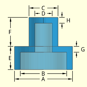
Inner Surface Area, Ainner,
Ainner = π D (F + G - H) + π B (E - G)
+ π(B2 - D2)/4
= π [ D (F + G - H) + B(E - G) + B2/4 ]
ATotal = Aouter + Ainner
Volume, V, consists of a single sphere.
V = πEA2/4 + πFC2/4
- πB2(E - G)/4 - πD2(F + G - H)/4
= π [A2 E + C2 F - B2 (E - G) - D2 (F + G - H)] / 4
| CAUTION |
Calculations do NOT check if
|
| Value | Equations | WE Program |
| Case 1 | ||
| Surface Area | 483.8 in2 | 483.8 in2 |
| Volume | 226.2 in3 | |
| Part Weight | 8.172 lb | 8.172 lb |
| Case 2 | ||
| Surface Area | 829.4 cm2 | 829.4 cm2 |
| Volume | 656.6 cm3 | |
| Part Weight | 1.448 lb | 1.448 lb |
| Case Number | ||
| Parameter | 1 | 2 |
| A | 10 in | 14 cm |
| B | 8 in | 10 cm |
| C | 5 in | 8 cm |
| D | 3 in | 4 cm |
| E | 4 in | 5 cm |
| F | 5 in | 5 cm |
| G | 1 in | 1 cm |
| H | 1 in | 2 cm |
| test density |
1 gm/cm3 | 1 gm/cm3 |
Conversion Constants to
determine part weight in lb
1 gm/cm3 = 2.2046×10⁻⁶ lb/mm3
= 0.036127 lb/in3
16 Dec 2020 - Kurt Gramoll
1) Equations were correct, but difficult to understand. New versions that match equations above were added to program.
The Sheath Hollow C Open is made from two hollow cylindrical sections. The top is assumed smaller than the bottom. The shape can have different wall thickness for each surface. The top and bottom is open.
Technical Calculations
The volume and outside surface area are based on two right cylinders, each with a hollow cylinder.
Outer Surface Area, Aouter,
Aouter = πCF + πAE + π(A2 - C2)/4
+ π(C2 - D2)/4+ π(A2 - B2)/4
= π (CF + AE + A2/2 - D2/4 - B2/4)
Inner Surface Area, Ainner,
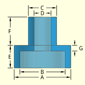
Ainner = π D (F + G) + π B (E - G) + π(B2 - D2)/4
= π [ D (F + G) + B(E - G) + B2/4 - D2/4 ]
ATotal = Aouter + Ainner
Volume, V, consists of a single sphere.
V = πEA2/4 + πFC2/4
- πB2(E - G)/4 - πD2(F + G)/4
= π [A2 E + C2 F - B2 (E - G) - D2 (F + G)] / 4
| CAUTION |
Calculations do NOT check if
|
| Value | Equations | WE Program |
| Case 1 | ||
| Surface Area | 479.1 in2 | 479.1 in2 |
| Volume | 219.1 in3 | |
| Part Weight | 7.916 lb | 7.916 lb |
| Case 2 | ||
| Surface Area | 829.4 cm2 | 829.4 cm2 |
| Volume | 631.5 cm3 | |
| Part Weight | 1.392 lb | 1.392 lb |
Conversion Constants to
determine part weight in lb
1 gm/cm3 = 2.2046×10⁻⁶ lb/mm3
= 0.036127 lb/in3
| Case Number | ||
| Parameter | 1 | 2 |
| A | 10 in | 14 cm |
| B | 8 in | 10 cm |
| C | 5 in | 8 cm |
| D | 3 in | 4 cm |
| E | 4 in | 5 cm |
| F | 5 in | 5 cm |
| G | 1 in | 1 cm |
| test density |
1 gm/cm3 | 1 gm/cm3 |
16 Dec 2020 - Kurt Gramoll
1) Equations were correct, but difficult to understand. New versions that match equations above were added to program.
The Sphere Hollow object is a simple spherical shape that is hollow. The wall thickness is given by the difference between A and B (and divided by 2).
The top and bottom vertical lines at the top and bottom do not technically exist. They are simply an artifact from the 3D modeling program.
Technical Calculations
Outer Surface Area, Aouter,
Aouter = π (4/3) (A/2)3
Inner Surface Area, Ainner,
Ainner= π (4/3) (B/2)3
ATotal = Aouter + Ainner
Volume, V, consists of two spheres,
V = π 4 [ (A/2)2 - (B/2)2 ]
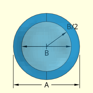
| Value | Equations | WE Program |
| Case 1 | ||
| Surface Area | 1,963 in2 | 1,963 in2 |
| Volume | 2,422 in3 | |
| Part Weight | 87.49 lb | 87.49 lb |
| Case 2 | ||
| Surface Area | 213.6 cm2 | 213.6 cm2 |
| Volume | 263.9 cm3 | |
| Part Weight | 0.5818 lb | 0.5818 lb |
| Case Number | ||
| Parameter | 1 | 2 |
| A | 20 in | 8 cm |
| B | 15 in | 2 cm |
| test density |
1 gm/cm3 | 1 gm/cm3 |
Conversion Constants to
determine part weight in lb
1 gm/cm3 = 2.2046×10⁻⁶ lb/mm3
= 0.036127 lb/in3
The Sphere Hollow object is a simple spherical shape that is solid.
Technical Calculations
Outer Surface Area, Aouter,
Aouter = π (4/3) (A/2)3
Inner Surface Area, Ainner, does not exist.
Ainner = 0
ATotal = Aouter + Ainner
Volume, V, consists of a single sphere.
V = π 4 (A/2)2
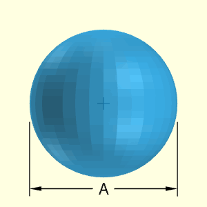
| Value | Equations | WE Program |
| Case 1 | ||
| Surface Area | 1,257 in2 | 1,257 in2 |
| Volume | 4,189 in3 | |
| Part Weight | 151.3 lb | 151.3 lb |
| Case 2 | ||
| Surface Area | 201.1 cm2 | 201.1 cm2 |
| Volume | 268.1 cm3 | |
| Part Weight | 0.5901 lb | 0.5901 lb |
| Case Number | ||
| Parameter | 1 | 2 |
| A | 20 in | 8 cm |
| test density |
1 gm/cm3 | 1 gm/cm3 |
Conversion Constants to
determine part weight in lb
1 gm/cm3 = 2.2046×10⁻⁶ lb/mm3
= 0.036127 lb/in3
The Spring object is a circular shaped spring that can have various turns or coils. The number of coils must be a whole integer value and greater than or equal to 1. Be careful not to have too many coils since the program does not check physical touching or interference between coils. The circular wire diameter of the spring is constant.
Note, the dimensions A and B are from the outside of the wire, not the center. The calculations subtract the radius when it calculates the wire length.

The spring volume and outside surface area are based on the spring wire length, L. It can be calculated by,
![]()
The Weight Estimator simulates a flat top and bottom by taking one less coil to calculate unwound L, and then adding the length of that one coil as if it was flat. The calculations assume complete coils (not partial coils) and the wire radius is subtracted from the outside coil diameter.
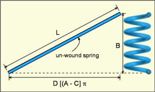
Outer Surface Area, Aouter, is calculated by using the spring L and its circumference or cross sectional area. The equation has an extra term 'C/2' to account for the two flat ends of the wire.
Aouter = π C (L + C/2)
Volume, V, of the spring is calculated by using the spring L and its circumference or cross sectional area,
V = (π C2/4) L
| Value | Equations | WE Program |
| Case 1 | ||
| Surface Area | 809.0 in2 | 809.0 in2 |
| Volume | 401.4 in3 | |
| Part Weight | 14.50 lb | 14.50 lb |
| Case 2 | ||
| Surface Area | 182.5 cm2 | 182.5 cm2 |
| Volume | 45.24 cm3 | |
| Part Weight | 0.09973 lb | 0.09973 lb |
| Case Number | ||
| Parameter | 1 | 2 |
| A | 12 in | 4 cm |
| B | 20 in | 10 cm |
| C | 2 in | 1 cm |
| D | 4 | 6 |
| test density |
1 gm/cm3 | 1 gm/cm3 |
Conversion Constants to
determine part weight in lb
1 gm/cm3 = 2.2046×10⁻⁶ lb/mm3
= 0.036127 lb/in3
The Support Plunger Solid is constructed with two cylindrical shapes. The bottom one is assumed to be thinner and acts like a support base.
Technical Calculations
The volume and outside surface area are based on two right cylinders, both solid.
Outer Surface Area, Aouter,
Aouter = πC2/4 + πCE + πA2/4 + πAB
+ π(A2 - C2)/4
Inner Surface Area, Ainner, does not exist.
Ainner = 0
ATotal = Aouter + Ainner
Volume, V, consists of a single sphere.
V = πEC2/4 + πBA2/4
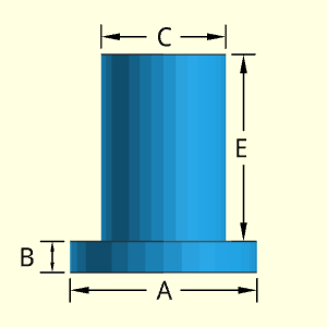
| Value | Equations | WE Program |
| Case 1 | ||
| Surface Area | 150.8 in2 | 150.8 in2 |
| Volume | 103.7 in3 | |
| Part Weight | 3.745 lb | 3.745 lb |
| Case 2 | ||
| Surface Area | 452.4 cm2 | 452.4 cm2 |
| Volume | 568.6 cm3 | |
| Part Weight | 1.254 lb | 1.254 lb |
| Case Number | ||
| Parameter | 1 | 2 |
| A | 6 in | 10 cm |
| B | 1 in | 4 cm |
| C | 4 in | 6 cm |
| E | 6 in | 9 cm |
| test density |
1 gm/cm3 | 1 gm/cm3 |
Conversion Constants to
determine part weight in lb
1 gm/cm3 = 2.2046×10⁻⁶ lb/mm3
= 0.036127 lb/in3
16 Dec 2020 - Kurt Gramoll
1) Equations included unused input variable, D. Default was zero so equations gave correct results, but confusing. New equations do not use D.
The Support Plunger Through is constructed with two hollow cylindrical shapes. The bottom one is assumed to be thinner and acts like a support base. The hollow circular hole is assumed to be the same diameter, D, in both sections.
Technical Calculations
The volume and outside surface area are based on two right cylinders with a hollow cylinder.
Outer Surface Area, Aouter,
Aouter = πC2/4 + πCE + πA2/4 + πAB
+ π(A2 - C2)/4 - 2 (D2)/4
= π(A2 - D2)/4 + π(CE + AB)
Inner Surface Area, Ainner,

Ainner = π D (B + E)
ATotal = Aouter + Ainner
Volume, V, consists of a single sphere.
V = πEC2/4 + πBA2/4 -πD2(E + B)/4
= π(EC2 + BA2 - ED2 - BD2)/4
| CAUTION |
Calculations do NOT check if
|
| Value | Equations | WE Program |
| Case 1 | ||
| Surface Area | 364.4 in2 | 364.4 in2 |
| Volume | 163.4 in3 | |
| Part Weight | 5.902 lb | 5.902 lb |
| Case 2 | ||
| Surface Area | 622.0 cm2 | 622.0 cm2 |
| Volume | 421.0 cm3 | |
| Part Weight | 0.9281 lb | 0.9281 lb |
| Case Number | ||
| Parameter | 1 | 2 |
| A | 8 in | 10 cm |
| B | 1 in | 4 cm |
| C | 6 in | 6 cm |
| D | 4 in | 4 cm |
| E | 8 in | 10 cm |
| test density |
1 gm/cm3 | 1 gm/cm3 |
Conversion Constants to
determine part weight in lb
1 gm/cm3 = 2.2046×10⁻⁶ lb/mm3
= 0.036127 lb/in3
The Upper Body shape is only one of two shapes that are over defined and causes an over constraint system (the other shape with this problem is Projectile Body).
If D is not used, then the shape can be determined, as shown in the diagram. The calculations do use D, so it has not be deleted from the Weight Estimator input page.
| CAUTION |
Should not be used - Shape is not physically possible with the given inputs. Needs to be removed or input variables reduced. |
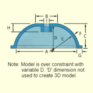

4 Jan 2021 - Kurt Gramoll
1) Equations not correct. Cannot update since the shape is not physically possible. Input variables need to be reduced.